
Improved circular ring turbine

A technology of turbines and rings, applied in mechanical equipment, engine components, machines/engines, etc., can solve the problems of rotor exposure safety, whether the airflow can be fully utilized, hidden dangers, etc., and achieve the effect of high airflow utilization.

Active Publication Date: 2020-04-10
YANGTZE UNIVERSITY
View PDF5 Cites 0 Cited by
  • Summary
  • Abstract
  • Description
  • Claims
  • Application Information

AI Technical Summary

Problems solved by technology

[0004] The purpose of the present invention is to overcome the above-mentioned technical deficiencies, provide an improved ring turbine, and solve the potential safety problems caused by the inability of the air flow energy to be fully utilized and the exposed rotor in the prior art

Method used


Image

  • Improved circular ring turbine
  • Improved circular ring turbine
  • Improved circular ring turbine

Examples


Embodiment Construction

[0017] The following will clearly and completely describe the technical solutions in the embodiments of the present invention with reference to the accompanying drawings in the embodiments of the present invention. Obviously, the described embodiments are only some, not all, embodiments of the present invention. Based on the embodiments of the present invention, all other embodiments obtained by persons of ordinary skill in the art without making creative efforts belong to the protection scope of the present invention.

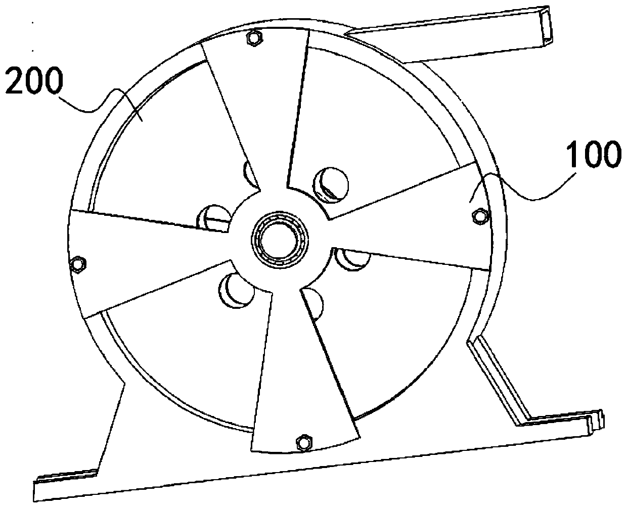
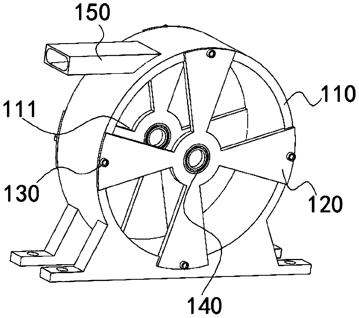
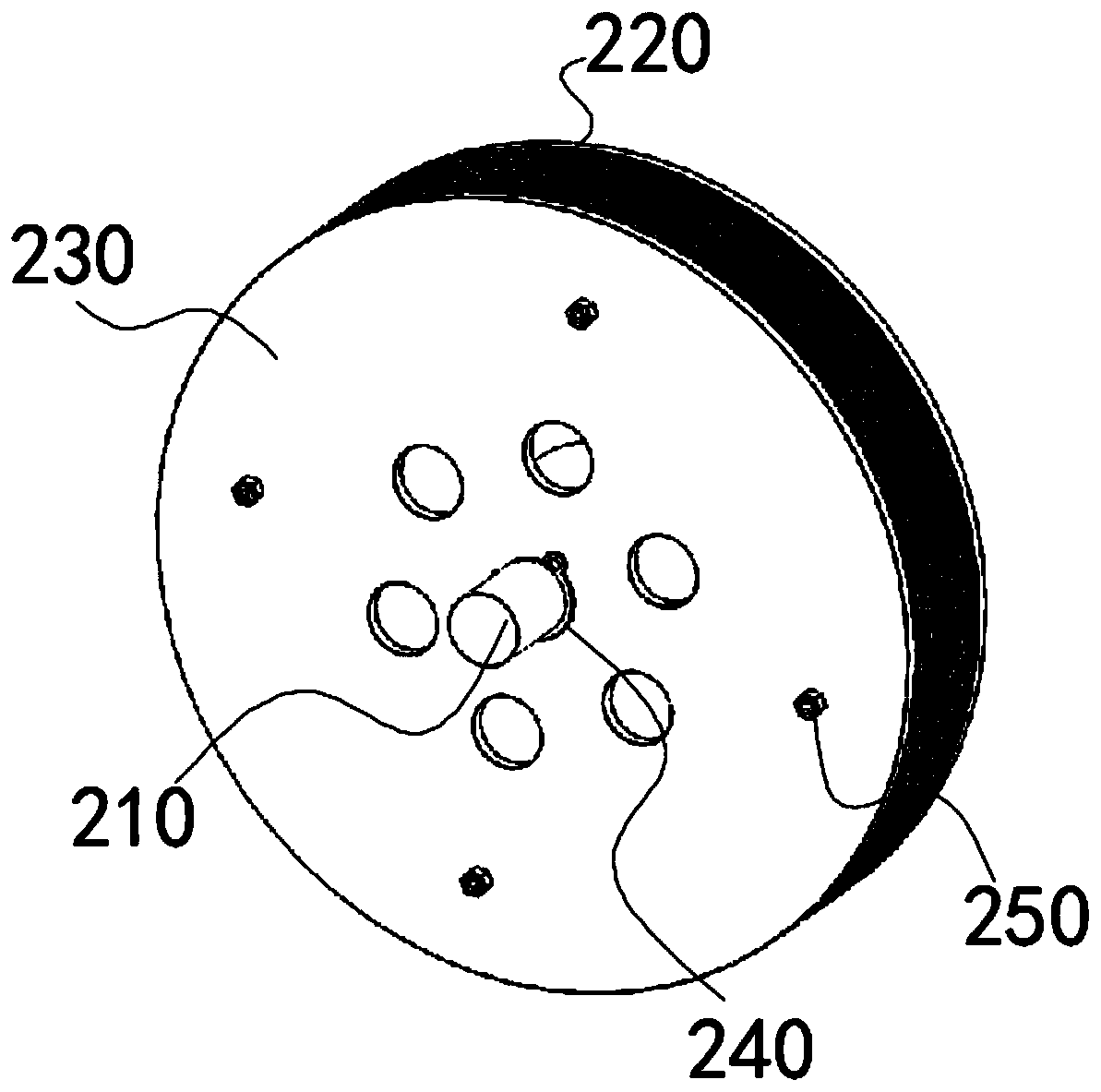
[0018] Such as figure 1 , image 3 , Figure 4 , Figure 9 and Figure 10 As shown, the present invention provides an improved ring turbine, including a casing assembly 100 and a rotor assembly 200, the casing assembly 100 has a rotating cavity 111, the rotor assembly 200 is built in the rotating cavity 111, and the rotor assembly 200 includes a rotating shaft 210, a plurality of rotating pieces 220, two clips 230 and a supporting circular tube 250, the ro...


PUM


Abstract

The invention discloses an improved circular ring turbine. The improved circular ring turbine comprises an outer shell assembly and a rotor assembly, wherein the outer shell assembly has a rotating cavity, the rotor assembly is arranged in the rotating cavity, the rotor assembly comprises a rotating shaft, a plurality of rotating pieces, two clamping pieces and a supporting circular pipe, the rotating shaft is rotatably connected with the outer shell assembly, the rotating pieces and the two clamping pieces are arranged on the rotating shaft in a sleeving mode, a clamping gap is formed betweenthe two clamping pieces, the plurality of rotating pieces are arranged in a stacked mode and arranged in the clamping gap, the rotating shaft is sleeved with the supporting circular pipe, and both ends of the supporting circular pipe are connected with clamping grooves formed in the two clamping pieces in a clamped mode respectively; and each rotating piece is a circular ring, a plurality of bulges are arranged on one side of each rotating piece, the plurality of bulges are uniformly arranged in the circumferential direction of each rotating piece, each bulge is close to the inner ring of each circular ring, an airflow pipeline is formed between every two adjacent bulges, and the thickness of the bulges is equal to a gap between every two adjacent rotating pieces. The improved circular ring turbine solves the problems that airflow kinetic energy cannot be fully utilized and potential safety hazards are caused by rotor exposure in the prior art.

Description

technical field [0001] The invention relates to the technical field of turbines, in particular to an improved ring turbine. Background technique [0002] A ring-shaped Tesla turbine is disclosed in Chinese patent CN201753619U. The annular Tesla turbine makes the rotor into a ring, and the inner side of the ring is evenly covered with annular thin slices. The nozzle extends into the inner side of the ring and sprays air to the ring along the tangential direction of the ring. The air flow will form a vortex under the guidance of the inner side of the ring. , because the annular sheet covering the inner side of the ring greatly increases the contact surface between the ring and the airflow, according to the boundary layer effect, the ring will be driven by the airflow to rotate together, thereby realizing the rotation of the rotor. [0003] According to the above design, the air flow sprayed into the rotor will produce centripetal motion due to deceleration, and then quickly l...

Claims


Application Information

Patent Timeline
IPC IPC(8): F01D1/22F01D5/04
CPCF01D1/22F01D5/04
Inventor 谢向东张建坤杜国锋
Owner YANGTZE UNIVERSITY
Learn More