Steel rail grinding equipment

A technology for rails and equipment, applied in the field of rail grinding equipment, can solve the problems of inconvenient operation, transportation and placement, large self-vibration, unfavorable wave grinding, etc., and achieves the effect of improving the grinding range, reducing the adverse effects and being easy to operate.

Pending Publication Date: 2020-05-01
山东博砺思轨道交通装备科技有限公司
View PDF0 Cites 4 Cited by
  • Summary
  • Abstract
  • Description
  • Claims
  • Application Information

AI Technical Summary

Problems solved by technology

This results in a larger size of the rail grinding wheel grinding equipment, which is inconvenient to operate, transport and install
At the same time, the existing grinding equipment uses an internal combustion engine as a power source, and its own vibration is large, which is not conducive to eliminating wave grinding, and will also generate noise and pollution

Method used


Image

  • Steel rail grinding equipment
  • Steel rail grinding equipment
  • Steel rail grinding equipment

Examples


no. 1 example

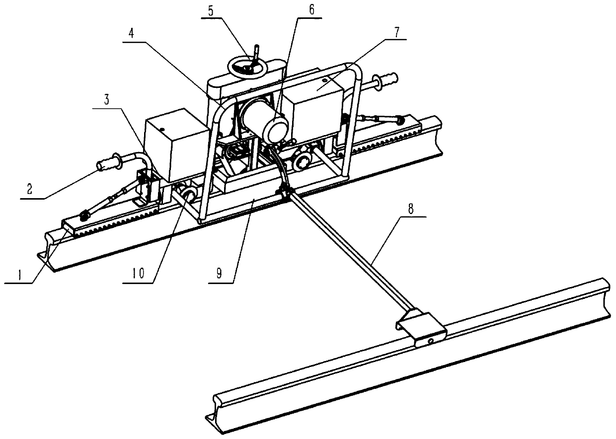
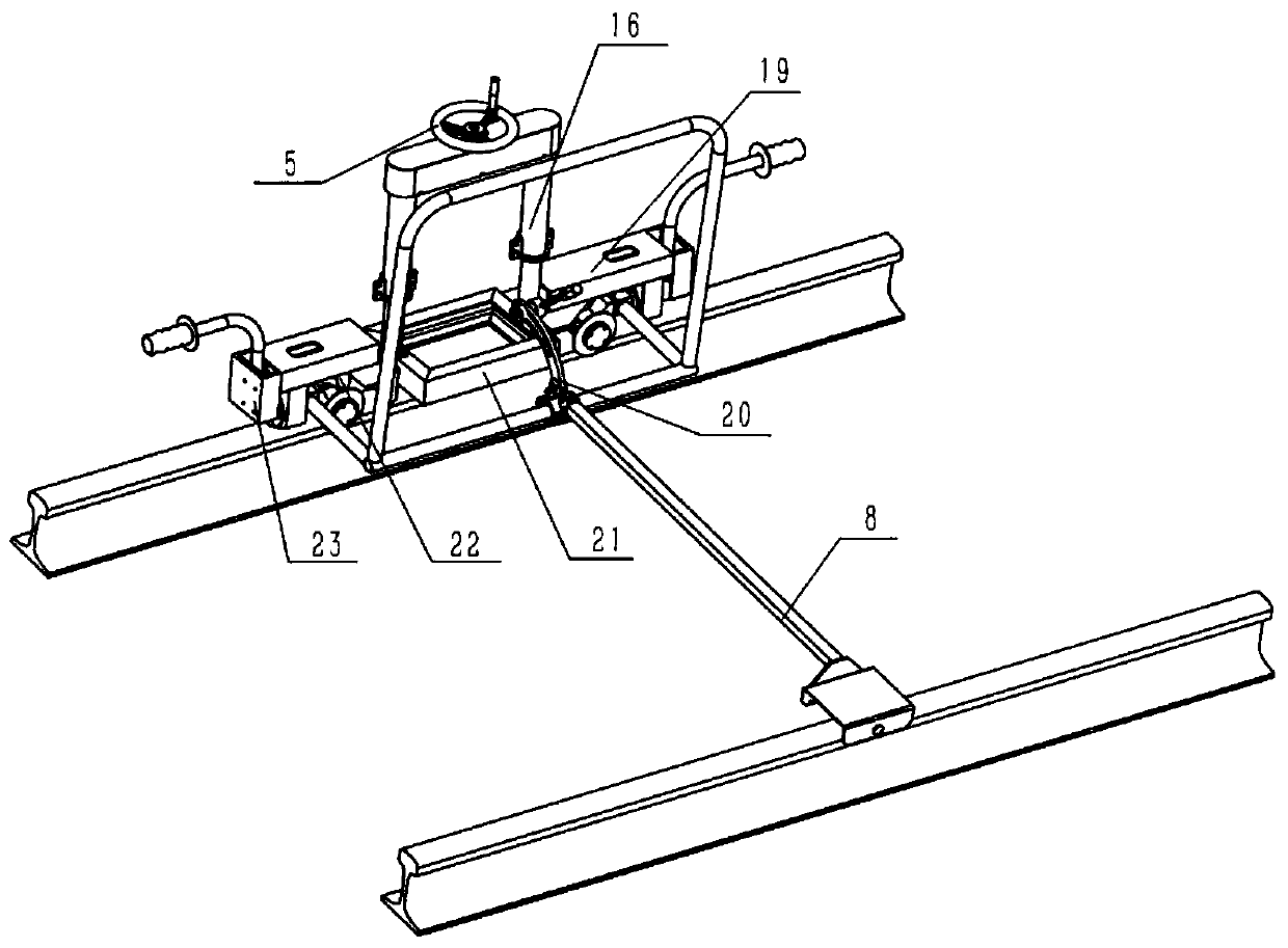
[0049] In order to realize the installation (or connection) between the sanding belt grinding device and the frame 9 (or specifically with the column 16), an arm extending horizontally from the column 14 to both sides (for example Figure 5 The element represented by 18 in ), the arm is provided with a connection structure 40, so that the abrasive belt grinding device is fixed or movably mounted on the column 16 in various possible ways such as fastening, snapping, surrounding, riveting and the like. Such as image 3 with 5 As best shown, the connecting structure 40 may be configured as two parts, both of which are of a semicircular configuration and capable of enclosing the post 16 therein when connected to each other.

no. 2 example

[0051] In order to realize that the abrasive belt grinding device can move in the height direction relative to the steel rail, the abrasive belt grinding device further includes a lifting mechanism.

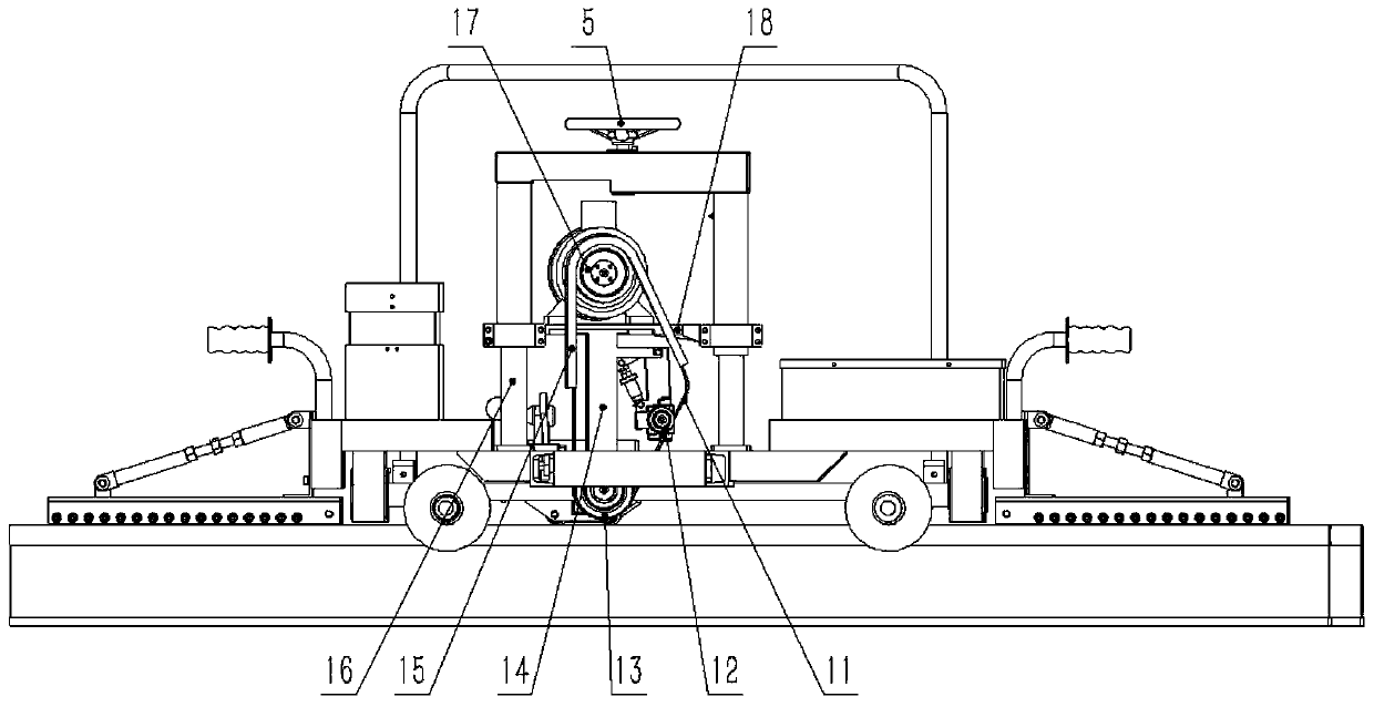
[0052] The lifting mechanism can at least drive the contact wheel 13 to move in the height direction (up and down). Alternatively, the lifting mechanism can drive the whole abrasive belt grinding device (including the abrasive belt 11, the driving wheel 17, the tensioning wheel 12 and the contact wheel 13) to move in the height direction. Since the above two movable connection modes are similar, here only the lifting mechanism drives the abrasive belt grinding device to move as a whole as an example for illustration. Those skilled in the art can think of other ways on this basis.

[0053] see Image 6 , in the illustrated embodiment, the lifting mechanism can drive the drive wheel 17, the tension wheel 12, the contact wheel 13 and the abrasive belt 11 on it to lift up and down ...


PUM


Abstract

The invention provides steel rail grinding equipment. The steel rail grinding equipment comprises a rack, a power supply device, an abrasive belt grinding device and a power providing device. According to the steel rail grinding equipment, the abrasive belt is adopted as a grinding tool, the actual contact area between the abrasive belt and the surface of the steel rail is large during grinding, and grinding efficiency is improved; due to the characteristics of the contact wheel rubber layer and the abrasive belt, the abrasive belt and the steel rail are in flexible contact during grinding operation, the influence of vibration of grinding equipment on the grinding quality can be reduced, and the grinding quality is improved; a corrugation roller structure is adopted, so that corrugation ofthe steel rail can be further effectively eliminated during grinding; deflection of the grinding device is completed through a swing guide groove and a guide groove nut, the structure is compact, andoperation is easy and convenient. Meanwhile, grinding is conducted in an electric mode, and operation is environmentally friendly and free of pollution.

Description

technical field [0001] The invention relates to the technical field of railway maintenance equipment, in particular to rail grinding equipment. Background technique [0002] Long-term operation of railway rails is prone to corrugation, which affects the stability and comfort of train operation. Therefore, it is necessary to grind the rails to eliminate or reduce corrugation. [0003] Traditional grinding equipment that eliminates or reduces corrugation mostly uses grinding wheels for grinding. However, the contact between the grinding wheel and the rail is a rigid contact, so the vibration is large. In addition, due to the particularity of corrugation damage, the crests and troughs of corrugation are not easily eliminated. Therefore, the existing rail grinding wheel grinding equipment needs to install rollers on both sides of the equipment to assist in grinding. This results in a larger size of the rail grinding wheel grinding equipment, which is inconvenient to operate, t...

Claims


Application Information

Patent Timeline
Patent Type & Authority Applications(China)
IPC IPC(8): E01B31/17
CPCE01B31/17
Inventor 樊文刚吕洪宾刘月明马金城樊文波
Owner 山东博砺思轨道交通装备科技有限公司
Why Eureka
Try Eureka