Scanning mechanism of laser thickness gauge
A technology of scanning mechanism and laser thickness measurement, which is applied in the direction of instruments, measuring devices, and optical devices, can solve the problems of mechanical vibration affecting data accuracy, save time for adjusting die heads, reduce material waste and energy waste, and realize The effect of precision and stability
- Summary
- Abstract
- Description
- Claims
- Application Information
AI Technical Summary
Problems solved by technology
Method used
Image
Examples
Embodiment 1
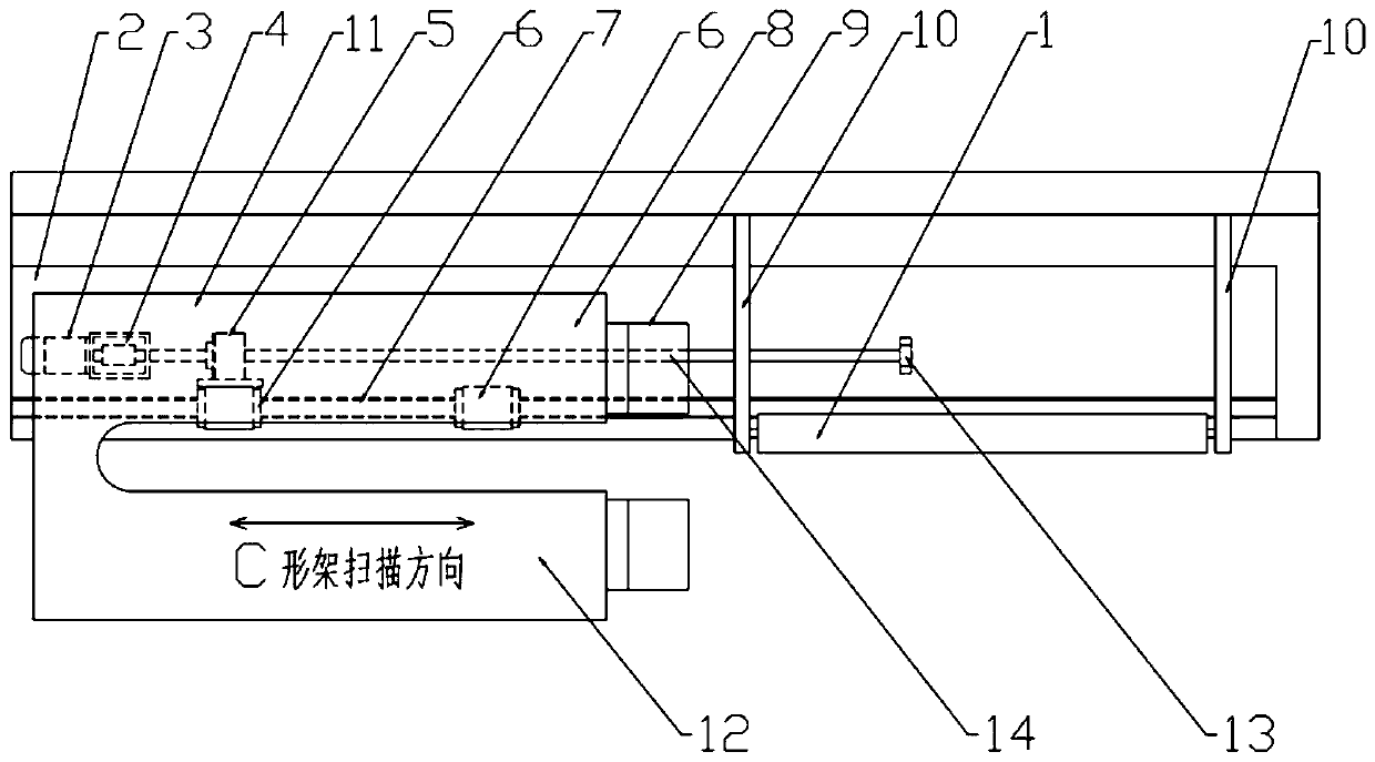
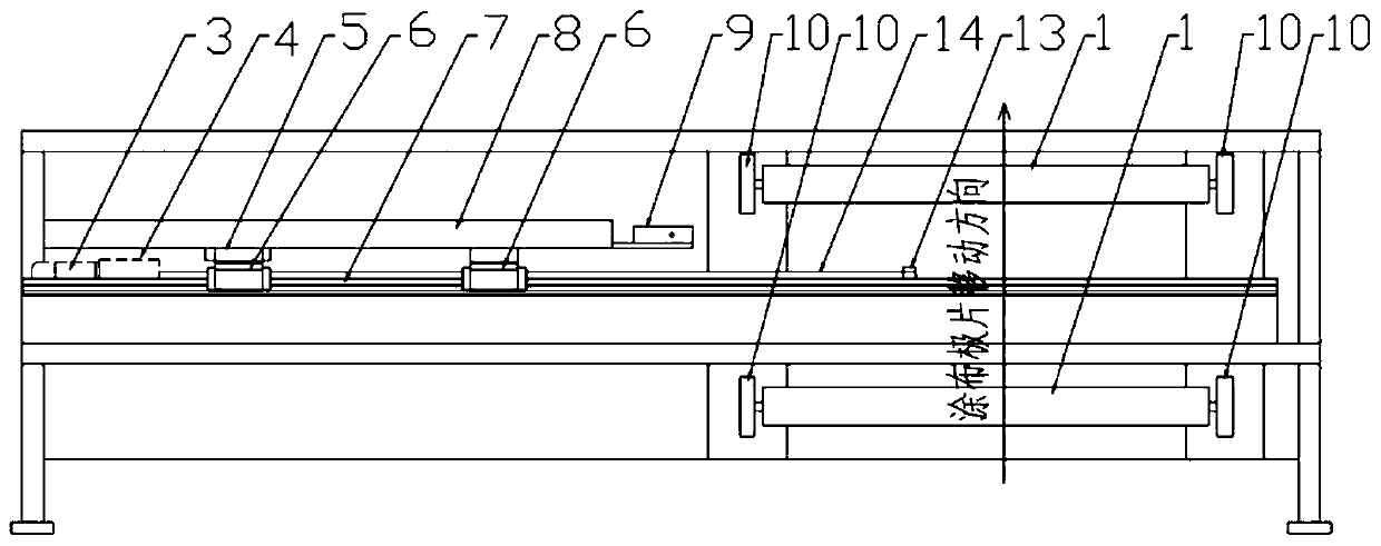
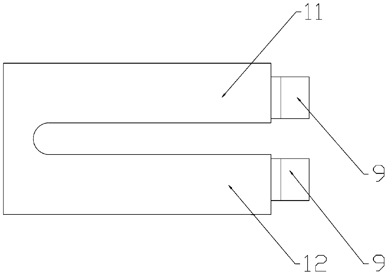
[0024] A scanning mechanism for a laser thickness gauge, comprising a mounting table 2, a C-shaped frame 8 is arranged on the mounting table 2, and the angle between the C-shaped frame 8 and the horizontal plane is within ±10° (this embodiment Take the C-shaped frame 8 as a horizontal setting for illustration, that is, the angle between the C-shaped frame 8 and the horizontal plane is 0°), and a group of laser sensors 9 for detecting thickness are provided on the C-shaped frame 8 .
[0025] A guide rail 7 is fixed on the installation table 2 , and a slide block 6 is arranged on the guide rail 7 , and the slide blocks 6 are all fixedly arranged on the C-shaped frame 8 . The mounting table 2 is provided with a servo motor 3, and the servo motor 3 is connected with a screw mandrel 14 through a coupling 4, and the screw mandrel 14 is provided with a lead screw nut 5, and the lead screw nut 5 is connected to the screw mandrel 14. The slide block 6 is connected and fixed to drive th...
Embodiment 2
[0028] The difference from the first embodiment above is that the center of gravity of the C-shaped frame 8 is on the left side frame 11 . The position of the center of gravity of the C-shaped frame 8 is set in a vertical plane passing through the axis of the guide rail 7 . Put the center of gravity on the left side frame 11, because the guide rail 7 is below the left side frame 11, the center of gravity falls in the vertical plane passing through the axis of the guide rail 7, and the left side frame 11 runs more smoothly, so that the left side frame of the C-shaped frame 8 11 and the mechanical vibration produced by the right frame 12 are smaller, which improves the measurement accuracy. If a double guide rail multi-slider structure is adopted, two guide rails are set under the left side frame 11 and the right side frame 12, and the parallelism of the two guide rails cannot be fully guaranteed. The sliders on the two guide rails are fixed on the C-shaped frame. Two sliders c...
PUM
 Abstract
Description
Claims
Application Information
 - R&D
- Intellectual Property
- Life Sciences
- Materials
- Tech Scout
- Unparalleled Data Quality
- Higher Quality Content
- 60% Fewer Hallucinations
Browse by: Latest US Patents, China's latest patents, Technical Efficacy Thesaurus, Application Domain, Technology Topic, Popular Technical Reports.
© 2025 PatSnap. All rights reserved.Legal|Privacy policy|Modern Slavery Act Transparency Statement|Sitemap|About US| Contact US: help@patsnap.com


