

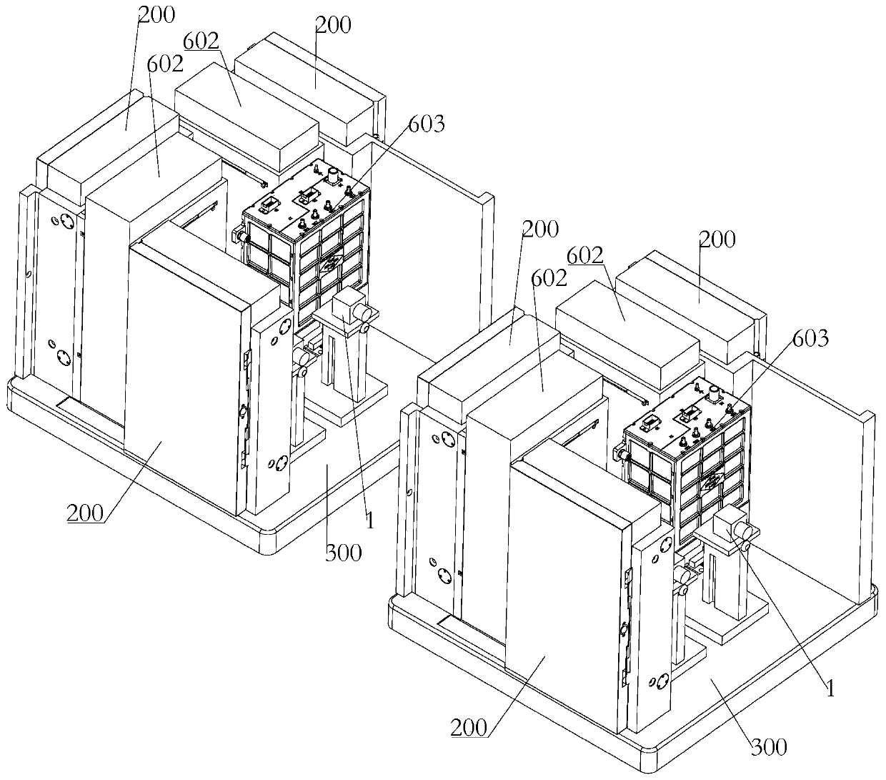
Mutual-inspection-type exposure device outside material cabin
A technology of lifting device and mounting seat, which is applied in the field of mutual inspection exposure device outside the cabin of materials, can solve the problems of no material space environment exposure support operation device, material test box and other problems, and achieve the effect of data collection
- Summary
- Abstract
- Description
- Claims
- Application Information
AI Technical Summary
Problems solved by technology
Method used
Image

Examples
Embodiment approach 1
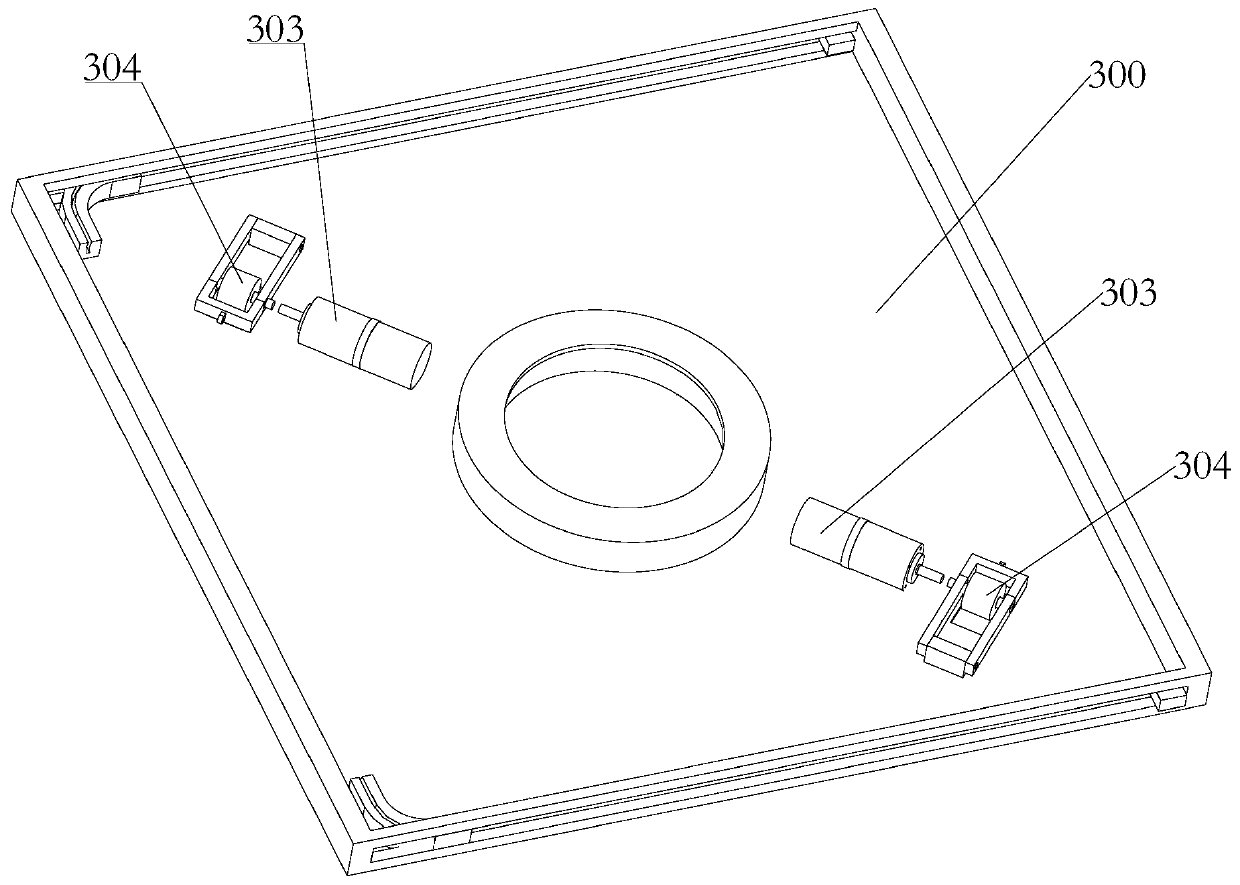
[0101] Such as figure 2 As shown, the rotating mechanism of this embodiment includes:
[0102] A driving motor 303, the driving motor 303 is installed on the force-bearing mechanism 300 and spaced apart from the base 600;
[0103] Friction wheel 304, the friction wheel 304 is installed at the drive end of the drive motor 303;
[0104] The upper surface of the base 600 has a friction surface for friction transmission with the friction wheel 304, the driving motor 303 drives the friction wheel 304 to rotate, and the friction wheel 304 rotates and moves around the center of the base 600 along the friction surface. In turn, the force-bearing mechanism 300, the test box 200 and the optical inspection device on it are driven to rotate around the center of the base 600.
[0105] Specific, such as figure 2 As shown, the driving end of the first driving motor 303 is arranged radially with the center of the base 600; there are two rotating mechanisms, and they are arranged symmetrically along...
Embodiment approach 2
[0107] The rotating mechanism of this embodiment includes two drive motors, one drive ring gear, and one drive gear. The two drive motors are mounted on the force-bearing mechanism and the drive ends thereof extend vertically downwards. The drive gear one Installed on the drive end of the driving motor two; the driving gear ring is installed in the middle of the base, the driving gear is meshed with the driving gear ring, and the driving motor two drives the driving gear to surround As soon as the driving gear ring makes a rotating movement, the force-bearing mechanism, the test box and the optical inspection device on it are driven to rotate around the center of the base. For details, refer to the third embodiment of the rotation mechanism, the structure of the rotation driving part and the driving gear in cooperation. The drive gear is used to cooperate with the drive gear ring to realize the rotation movement, and the structure is simple and easy to realize.
Embodiment approach 3
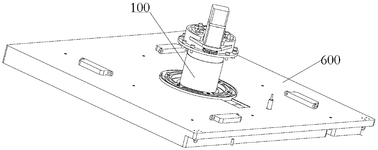
[0109] Such as Figure 3-Figure 12 As shown, the rotating mechanism of this embodiment needs to be implemented in cooperation with a lifting device. Specifically, the lifting device 100 is installed on the base 600, and the lifting end of the lifting device 100 is connected to the rotating mechanism and drives the Rotating mechanism rises and falls. The setting of the lifting device can facilitate the avoidance of structures such as the antenna in the space station during the rotation.
[0110] Among them, a specific solution for the lifting device 100 is, such as Figure 3-Figure 12 As shown, the lifting device includes:
[0111] Drive slip ring 101, said drive slip ring 101 is installed at the drive end of the lift drive portion 112 and rotates under the drive of the lift drive portion 112, and a spiral slide 107 is provided on the side wall of the drive slip ring 101;
[0112] Lifting slip ring 102, the lifting slip ring 102 is sleeved in the driving slip ring 101, the lifting sl...
PUM
 Abstract
Description
Claims
Application Information