Optical measurement system

An optical measurement system and light technology, applied in the field of leveling and focusing, can solve the problems of low measurement efficiency of silicon wafers, and achieve the effect of ensuring measurement efficiency and signal-to-noise ratio, fewer types of components, and simple structure

Active Publication Date: 2020-05-01
SHANGHAI MICRO ELECTRONICS EQUIP (GRP) CO LTD
View PDF5 Cites 1 Cited by
  • Summary
  • Abstract
  • Description
  • Claims
  • Application Information

AI Technical Summary

Problems solved by technology

[0006] In view of this, an embodiment of the present invention provides an optical measurement system to solve

Method used


Image

  • Optical measurement system
  • Optical measurement system
  • Optical measurement system

Examples


Embodiment Construction

[0062] In order to make the purpose, technical solution and advantages of the present invention clearer, the technical solution of the present invention will be fully described below through specific implementation in combination with the drawings in the embodiments of the present invention. Apparently, the described embodiments are some embodiments of the present invention, rather than all embodiments. Based on the embodiments of the present invention, all other embodiments obtained by persons of ordinary skill in the art without making creative efforts, All fall within the protection scope of the present invention.

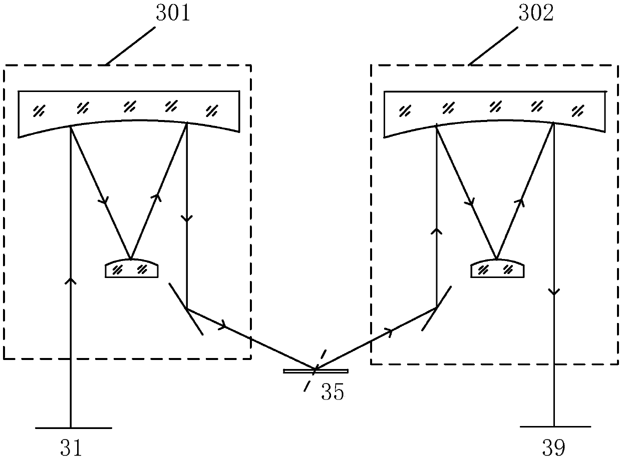
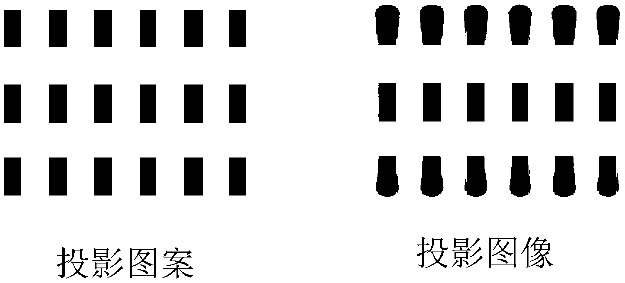
[0063] figure 2 A structural schematic diagram of an optical measurement system in the prior art, image 3 Yes figure 2 Schematic diagram of the comparison between the projected pattern and the projected image in the provided optical measurement system, such as figure 2 and image 3 As shown, the optical measurement system in the prior art may include a p...


PUM


Abstract

The embodiment of the invention discloses an optical measurement system. The system comprises a light source unit, an illumination unit, a projection pattern unit, a projection branch circuit, a detection branch circuit and a detector, wherein the projection branch comprises at least one projection concave reflecting mirror and a projection convex reflecting mirror, the projection concave reflecting mirror and the projection convex reflecting mirror are of offset structures, the detection branch comprises at least one detection concave reflector and one detection convex reflector, the detection concave reflector and the detection convex reflector are of offset structures, a pattern surface and a receiving plane of the projection pattern unit meet the Schempflug condition, and a receiving plane and a detection surface of the detector meet the Schempflug condition. The system is advantaged in that the projection branch circuit and the detection branch circuit are arranged to be of offsetstructures, the pattern surface and the receiving plane of the projection pattern unit meet the Schempflug condition, the receiving plane and a detection surface of the detector meet the Schempflug condition, the Schempflug condition is combined with an Offner structure, measurement efficiency and a signal-to-noise ratio of the optical measurement system are ensured, and the optical measurement system is few in element variety and simple in structure.

Description

technical field [0001] Embodiments of the present invention relate to the technical field of leveling and focusing of projection exposure equipment, and in particular, to an optical measurement. Background technique [0002] A projection lithography machine is a device that images the pattern on the mask onto the silicon wafer surface through the projection objective lens for lithography. The silicon wafer surface must be accurately located at the specified position to be exposed. In order to achieve this purpose, it needs to be precisely controlled by the automatic focusing and leveling system (FLS). Its working principle is to measure the surface height and inclination information of the silicon wafer surface, and feed back to the workpiece table through the controller, and the workpiece table moves the silicon wafer surface to ensure that the silicon wafer surface is at the best focal plane of the projection objective lens during the exposure process. [0003] In order t...

Claims


Application Information

Patent Timeline
IPC IPC(8): G03F9/00G01B11/06G01B11/27
CPCG01B11/0608G01B11/272G03F9/7026G03F9/7034G03F9/7088
Inventor 毛静超徐荣伟庄亚政孙建超季桂林
Owner SHANGHAI MICRO ELECTRONICS EQUIP (GRP) CO LTD
Why Eureka
Try Eureka