Control system switching device and method

A control system and switching device technology, applied in general control systems, control/adjustment systems, instruments, etc., can solve problems such as control system switching delay, impact on normal operation of locomotives, and impact on normal operation of locomotives, to achieve automatic switching and reduce switching untimely effect

Inactive Publication Date: 2020-05-01
ZHUZHOU CSR TIMES ELECTRIC CO LTD
View PDF19 Cites 0 Cited by
  • Summary
  • Abstract
  • Description
  • Claims
  • Application Information

AI Technical Summary

Problems solved by technology

[0005] In practical applications, the user can switch the control system according to the fault prompt information on the display screen, but when the microcomputer control system fails but the fault information is not displayed on the display screen, the user will not be able to know that the control system is faulty. The user will not perform the operation of flipping the transfer switch, which will cause the microcomputer system to stop working when it fails, affecting the normal operation of the locomotive
[0006] And the way of manually switching the control system is adopted. When the user does not know the prompt information of the control system failure in time, for example, when the user is not in front of the display screen, the fault prompt information displayed on the display screen cannot be found in time, and the control system will be affected. Switching brings delay, which affects the normal operation of the locomotive

Method used


Image

  • Control system switching device and method
  • Control system switching device and method
  • Control system switching device and method

Examples


Embodiment Construction

[0038] The following will clearly and completely describe the technical solutions in the embodiments of the present invention in conjunction with the accompanying drawings in the embodiments of the present invention. Obviously, the described embodiments are only some of the embodiments of the present invention, not all of them. Based on the embodiments of the present invention, all other embodiments obtained by persons of ordinary skill in the art without making creative efforts belong to the protection scope of the present invention.

[0039] In order to enable those skilled in the art to better understand the solution of the present invention, the present invention will be further described in detail below in conjunction with the accompanying drawings and specific embodiments.

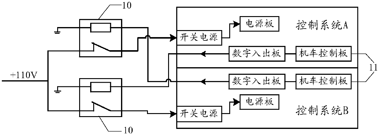
[0040] Next, a control system switching device provided by an embodiment of the present invention is introduced in detail. figure 2 A schematic structural diagram of a control system switching devic...


PUM


Abstract

The embodiment of the invention discloses a control system switching device. The control system switching device comprises a switch component and a controller connected with the switch component; a power supply is connected to two control systems through the switch component; the controller is used to determine a master control system and a backup control system from the two control systems according to a preset rule after a system is powered on, and control the switch component to communicate with the master control system; and when the master control system fails, the switch component is controlled to be switched to communicate with the standby control system. The device adopts an automatic switching mode; when a fault occurs in the running control system, the controller realizes the automatic switching of the control system by adjusting the on-off between the switch component and the control system, thereby effectively reducing the influence caused by untimely switching of the control system in the prior art. In addition, the invention also provides a control system switching method, and the effect is as above.

Description

technical field [0001] The invention relates to the technical field of locomotive control, in particular to a control system switching device and method. Background technique [0002] The microcomputer control system of SS9G locomotive is mainly TPY01 microcomputer cabinet, and the TPY01 microcomputer control system is mainly composed of microcomputer cabinet and control box. Among them, the control box is the core part of the microcomputer control system, and there are two identical control systems of A and B. [0003] In the prior art, the redundant switching mode of the microcomputer control system is to switch the power sources of the control systems of groups A and B through the mechanical power switch KN1. The transfer switch KN1 has an interlock function, which only allows the control system of group A or B in the control system to be energized to work, so as to realize the cold standby redundancy of the control system. The schematic diagram of its structure is as fo...

Claims


Application Information

Patent Timeline
IPC IPC(8): G05B9/03
CPCG05B9/03
Inventor 谢佳彬郭建苏伟
Owner ZHUZHOU CSR TIMES ELECTRIC CO LTD
Why Eureka
Try Eureka