Supercharge Your Innovation With Domain-Expert AI Agents!

In-display fingerprint recognition device, LCD fingerprint recognition system, electronic equipment and light guide film

A technology for fingerprint identification and electronic equipment, applied in character and pattern recognition, instruments, computer parts, etc., can solve the problems of occupying the width and size of the chin area of ​​the mobile phone, affecting the proportion of the mobile phone screen, and the width of the chin area, etc.

Active Publication Date: 2020-05-01
SHENZHEN GOODIX TECH CO LTD
View PDF7 Cites 2 Cited by
  • Summary
  • Abstract
  • Description
  • Claims
  • Application Information

AI Technical Summary

Problems solved by technology

Since the infrared light source is installed in the chin area of ​​the electronic product through the flexible circuit board, it will occupy the width of the chin area of ​​the mobile phone, resulting in the widening of the chin area of ​​the mobile phone screen, thereby affecting the overall screen-to-body ratio of the mobile phone, making the screen-to-body ratio of the mobile phone significantly reduced
[0004] However, since the width of the infrared light source, the thickness of the flexible circuit board connected to the infrared light source, and the thickness of the glue that the infrared light source is attached to the middle frame of an electronic product such as a mobile phone are all limit size requirements, it is difficult to make it narrower , so will result in wider chin area for electronics

Method used


Image

  • In-display fingerprint recognition device, LCD fingerprint recognition system, electronic equipment and light guide film
  • In-display fingerprint recognition device, LCD fingerprint recognition system, electronic equipment and light guide film
  • In-display fingerprint recognition device, LCD fingerprint recognition system, electronic equipment and light guide film

Examples


Embodiment 1

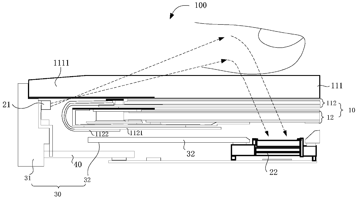
[0088] figure 2 It is a schematic structural diagram of the first mobile phone equipped with an under-screen fingerprint recognition device provided in Embodiment 1 of the present application, image 3 It is a schematic structural diagram of the second mobile phone equipped with an under-screen fingerprint recognition device provided in Embodiment 1 of the present application, Figure 4 It is a schematic diagram of the positional relationship between a light guide film and a first circuit board provided in Embodiment 1 of the present application, Figure 5 It is a schematic diagram of the positional relationship between another light guide film and the first circuit board provided in Embodiment 1 of the present application.

[0089] refer to Figure 2 to Figure 5 As shown, the present application provides an under-screen fingerprint identification device 20, which is applied to an electronic device having a liquid crystal display screen 10. The fingerprint detection area (n...

Embodiment 2

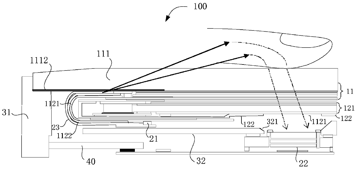
[0146] Figure 20 It is a schematic structural diagram of the first mobile phone equipped with an under-screen fingerprint recognition device provided in Embodiment 2 of the present application. Figure 21 It is a partial structural schematic diagram of the second mobile phone equipped with an under-screen fingerprint recognition device provided in Embodiment 2 of the present application.

[0147] On the basis of the above examples, refer to Figure 20 and Figure 21As shown, in this embodiment, the light receiving end 233 of the light guide film 23 is attached to the surface of the first circuit board 1121 and is located below the liquid crystal display screen 10, and the light receiving end 233 is opposite to the light emitting surface of the detection light source 21. The difference between this embodiment and the first embodiment above is that in this embodiment, the light emitting end 234 is attached to the inner wall of the middle frame 30 of the electronic device, and...

Embodiment 3

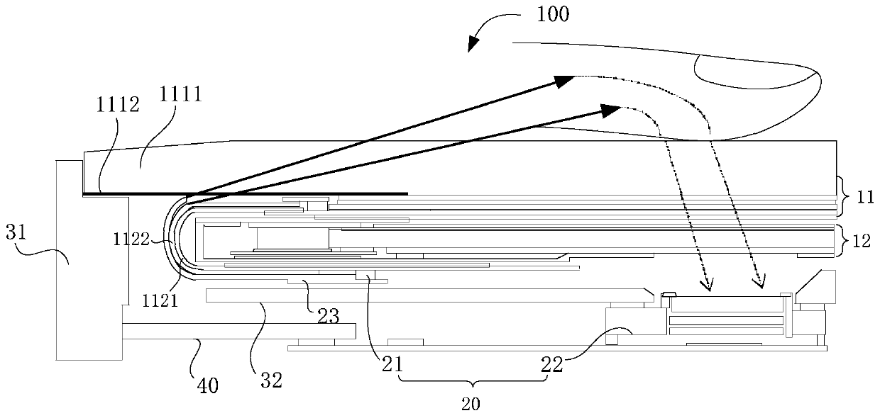
[0156] Figure 22 It is a schematic structural diagram of the first mobile phone equipped with an under-screen fingerprint recognition device provided in Embodiment 3 of the present application. Figure 23 It is a partial structural schematic diagram of the second mobile phone equipped with an under-screen fingerprint recognition device provided in Embodiment 3 of the present application.

[0157] On the basis of the above-mentioned embodiment 1 and embodiment 2, the difference from the above-mentioned embodiment 1 and embodiment 2 is that in this embodiment, refer to Figure 22 and Figure 23 As shown, in this embodiment, the detection light source 21 is attached to the second circuit board 40, the light receiving end 233 of the light guide film 23 is attached to the second circuit board 40, and the light emitting end 234 is attached to an electronic device such as a mobile phone 100 The inner wall of the middle frame 30 is attached to the inner wall of the middle frame 30 ...


PUM


Abstract

The application provides an in-display fingerprint recognition device, an LCD fingerprint recognition system, electronic equipment and a light guide film. The in-display fingerprint recognition deviceis applied to the electronic equipment that has a liquid crystal display screen, and the fingerprint detection area of the in-display fingerprint recognition device is at least partially located at the display area of the liquid crystal display screen. The in-display fingerprint recognition device comprises a detection light source, a fingerprint recognition module and a light guide film, whereinthe detection light source and the fingerprint recognition module are both positioned below the liquid crystal display screen. The detection light emitted by the detection light source is guided to alight emitting end through the light guide film to make the detection light irradiates a finger above the fingerprint detection area through the light emitting end to form fingerprint detection lightthat carries fingerprint information, and a fingerprint recognition module receives the fingerprint detection light that penetrates through a light transmission area in order to acquire an fingerprint image of the finger, thereby help to reduce the regional width of the chin of a current electronic product while realizing in-display fingerprint recognition.

Description

technical field [0001] The present application relates to the technical field of fingerprint identification, in particular to an under-screen fingerprint identification device, a liquid crystal display screen fingerprint identification system, electronic equipment and a light guide film. Background technique [0002] With the development of full-screen smartphones, mobile phones have higher and higher requirements for screen-to-body ratio, and the fingerprint recognition technology under the screen has become a trend. [0003] At present, mobile phones using liquid crystal display (LCD) screens need to use infrared light sources to supplement the light. The infrared light emitted by the infrared light source shines on the finger above the fingerprint detection area on the liquid crystal display screen, and forms a fingerprint carrying fingerprint through the finger. The fingerprint detection light of the information is received by the fingerprint recognition module to realiz...

Claims


Application Information

Patent Timeline
Patent Type & Authority Applications(China)
IPC IPC(8): G06K9/00G06K9/20
CPCG06V40/1324G06V10/141
Inventor 张胜斌熊峰刘文拯
Owner SHENZHEN GOODIX TECH CO LTD
Features
  • R&D
  • Intellectual Property
  • Life Sciences
  • Materials
  • Tech Scout
  • Unparalleled Data Quality
  • Higher Quality Content
  • 60% Fewer Hallucinations
Learn More