A kind of ultrasonic soldering method

An ultrasonic and soldering technology, applied in welding equipment, manufacturing tools, metal processing, etc., can solve problems such as inconsistent thickness, inability to align and connect pads, and unreliable connection between chips and substrates

Active Publication Date: 2021-09-14
广州市鸿利显示电子有限公司
View PDF0 Cites 0 Cited by
  • Summary
  • Abstract
  • Description
  • Claims
  • Application Information

AI Technical Summary

Problems solved by technology

[0003] In the existing mini LEDs, tin is generally placed on the pads of the substrate by brushing solder paste. Due to the small size of the mini LED, the size of the corresponding pads is also relatively small. If the paste does not fall on the pad area, it will lead to the problem of unreliable connection, and at the same time, the amount of tin on the pad cannot be accurately controlled; this will cause the thickness of tin on adjacent pads to be inconsistent, and if the amount of tin Too little will lead to unreliable connection between the chip and the substrate, and too much tin will easily move the chip on the substrate when the chip is soldered to the substrate, which will cause the pads of the chip and the pads on the substrate to be out of alignment and connection, resulting in unreliable connection

Method used


Image

  • A kind of ultrasonic soldering method
  • A kind of ultrasonic soldering method
  • A kind of ultrasonic soldering method

Examples


Embodiment Construction

[0041] The present invention will be described in further detail below in conjunction with the accompanying drawings and specific embodiments.

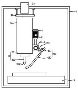
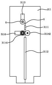
[0042] Such as Figure 1-4 As shown, an ultrasonic soldering method is used to weld tin wire through an ultrasonic soldering device. The ultrasonic soldering device includes a frame 1, a heating device 2, a discharge mechanism 3 and an ultrasonic mechanism 4; the discharge mechanism 3 is arranged on the upper end of the frame 1 , the heating device 2 is arranged at the lower end of the frame 1; the ultrasonic mechanism 4 is connected with the discharging mechanism 3; the substrate is placed on the heating device 2. In this embodiment, the heating device 2 is a heating table.

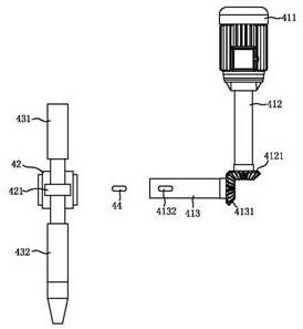
[0043] Ultrasonic mechanism 4 comprises ultrasonic driving assembly 41, rotating part 42 and ultrasonic device 43; Ultrasonic driving assembly 41 is connected with rotating part 42; Rotating part 42 is connected with ultrasonic device 43; 43 turns.

[0044] The...


PUM


Abstract

The invention provides an ultrasonic soldering method, comprising an ultrasonic soldering device, the ultrasonic soldering device includes a frame, a heating device, a discharging mechanism and an ultrasonic mechanism; the discharging mechanism is arranged at the upper end of the frame, and the heating device is arranged at the lower end of the frame; the ultrasonic mechanism It is connected with the discharge mechanism; the present invention controls the amount of tin when soldering is different through the different sizes of the pads; avoiding that the size of the pads is large and the amount of tin is too small, causing the LED chip to be unable to be firmly welded on the pads; at the same time, it can avoid If the size of the pad is too small and the amount of tin is too much, the LED chip moves on the pad, resulting in unreliable connection; soldering through an ultrasonic mechanism can accurately control the amount of tin with high precision.

Description

technical field [0001] The invention relates to the field of Mini LEDs, in particular to an ultrasonic soldering method. Background technique [0002] Mini LED refers to LEDs with a package size of 0.1-0.2mm, also known as sub-millimeter light-emitting diodes. Since the size of mini LED is on the order of 100 microns, while the size of the existing Micro LED is about 50 microns, its size is slightly larger than that of the existing Micro LED. Its mass production is feasible and can be applied to the backlight of large-sized displays. . Due to its small size and flexible substrate, mini LED can also achieve a form of high-curved backlight. It adopts a local dimming design, which has better color rendering, and can bring more refined HDR partitions to LCD panels, and its thickness is also close to that of OLED. It can save power by up to 80%. Therefore, it is suitable for applications such as mobile phones, TVs, car panels, and gaming notebooks to meet the needs of backlight...

Claims


Application Information

Patent Timeline
Patent Type & Authority Patents(China)
IPC IPC(8): B23K1/005B23K3/00B23K3/08
CPCB23K1/005B23K3/00B23K3/08
Inventor 雷浩陈永铭李文涛
Owner 广州市鸿利显示电子有限公司
Why Eureka
Try Eureka