Supercharge Your Innovation With Domain-Expert AI Agents!

Numerical control spindleless rotary cutting device

A technology of rotary cutting device and clamping shaft, which is applied in the manufacture of veneer, wood processing appliances, manufacturing tools, etc. The effect of production efficiency and veneer quality, improving thickness accuracy and surface quality, and high veneer yield

Pending Publication Date: 2020-05-05
SHANDONG BAISHENGYUAN GRP
View PDF4 Cites 0 Cited by
  • Summary
  • Abstract
  • Description
  • Claims
  • Application Information

AI Technical Summary

Problems solved by technology

[0002] As we all know, due to the scarcity of forests in recent years, the diameter of logs used for plywood production is relatively small, and many planted trees are also used for plywood production, so the raw materials for plywood production are gradually smaller than the previous production logs. The production of veneer with single card shaft or double card shaft has relatively low production cost and production efficiency, and is not suitable for the current production demand. Based on the above reasons, a CNC non-card shaft rotary cutting machine has been developed and designed. The traditional non-card shaft rotary cutting machine The substantial disadvantages of this structure are:
[0003] 1. Since the previous non-card shaft rotary cutting machine has a pressure gauge roller at the front end of the pressure gauge frame above the blade, the diameter of the pressure gauge roller should be as small as possible according to the principle of wood cutting. However, due to the limitation of the pressure gauge roller strength and bearing size , the diameter of the pressure gauge roller is generally greater than 80mm, so that the single roller is in contact with the outer circle of the log, and there must be a certain board clearance with the back of the knife. The centerline of the single roller of this structure is about 15mm higher than the blade, so that The contact extrusion area between the roller and the log is too high above the blade, so there is no real extrusion on the rotary cut veneer, and the quality of the rotary cut veneer is very poor
[0004] 2. During the rotary cutting process, the diameter of the log gradually decreases, and the radius of curvature gradually decreases. The contact area between the single roller and the log decreases with the diameter, and the contact point gradually becomes higher. The quality of the veneer that is rotary cut is poor, and the surface The finish is low, and the veneer with large thickness is prone to back cracks on the back of the veneer. Moreover, the wood of different tree species is different in hardness and softness after rotary cutting, and the thickness error of the veneer produced is also large. Therefore, so far, no veneer on the market A large part of the veneer cut by the card shaft cannot meet the quality requirements for the production of high-grade plywood, especially when the veneer is cut to a small diameter, the quality of the veneer is even worse
[0005] 3. When the log is rotary cut, because the drive roller drives the motor to rotate at a constant speed, when the wood core is small, the feed speed is fast and the impact force is large, which seriously affects the service life of the single and double rollers.
When working, first manually adjust the gap between the two knife gates of the plate pressure ga

Method used


Image

  • Numerical control spindleless rotary cutting device
  • Numerical control spindleless rotary cutting device
  • Numerical control spindleless rotary cutting device

Examples


Embodiment Construction

[0046] The present invention will be described below in conjunction with the accompanying drawings.

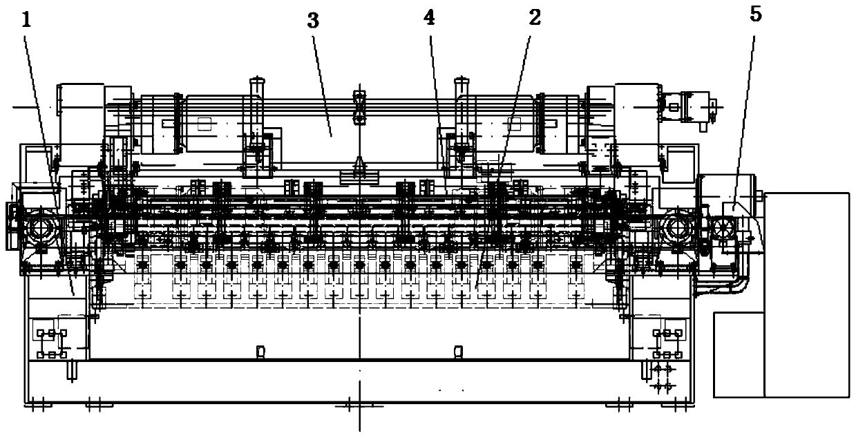
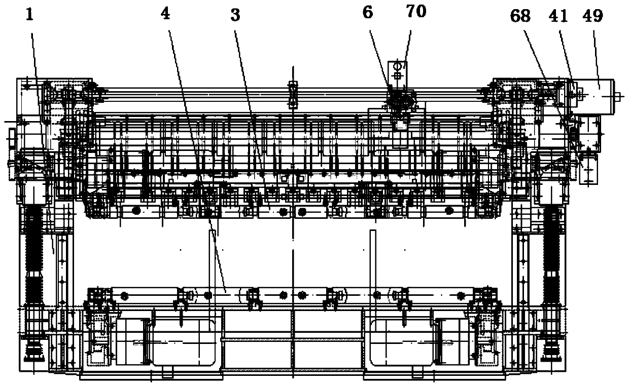
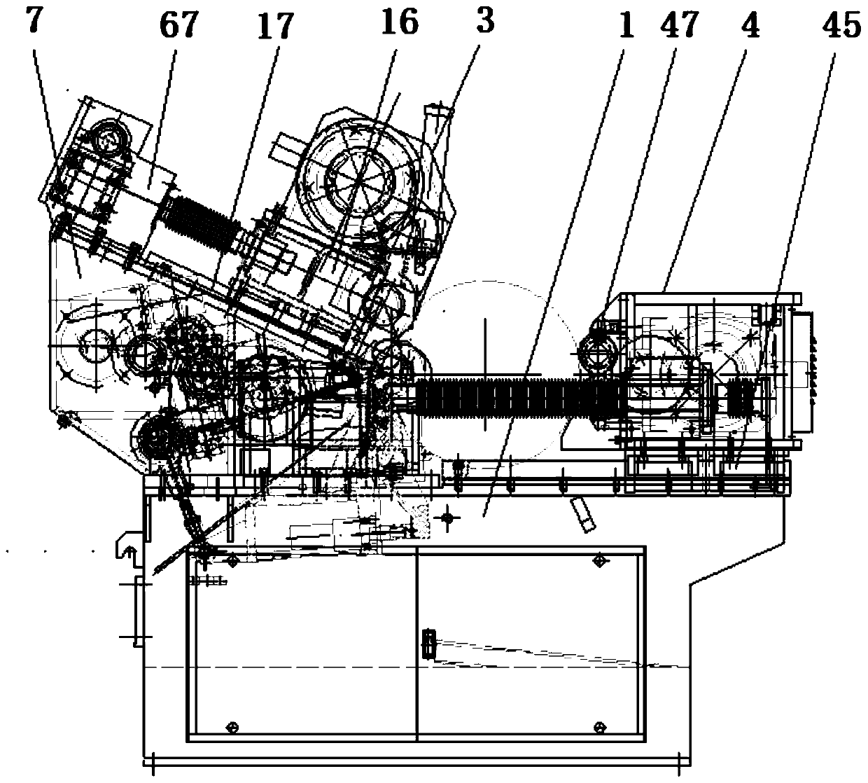
[0047] As shown in the accompanying drawings, a numerical control shaft-free rotary cutting device includes a machine base 1, a rotary knife device 2, a single-roller device 3, a double-roller device 4 and a PLC frequency conversion control system 5, and the double-roller device 4 is slid The block is rollingly connected with the linear guide rail provided on the machine base 1, the plate pressure device 6 is provided between the rotary knife device 2 and the single roller device 3, and the upper end of the machine base 1 at both ends of the rotary knife device 2 is provided with a fixed frame 7. The fixed frame 7 is provided with a rotary sleeve of a tool holder body, an inclined track and a single-roller feed transmission device, and the inner side of the fixed frame 7 is provided with a pressure gauge slideway 11, and the two ends of the double-roller device are respectively...


PUM


Abstract

The invention discloses a numerical control spindleless rotary cutting device. The numerical control spindleless rotary cutting device comprises a machine base, a rotary cutter device, a single rollerdevice, a plate pressure gauge device, a fixed frame, a cutter frame body rotating sleeve, an inclined plane track, a single roller feeding transmission device, a double-roller device and a PLC frequency conversion control system, and is characterized in that the plate pressure gauge device further comprises a pressure gauge frame rotary fan-shaped worm wheel and a worm servo drive device, wherein a pressure gauge rotating shaft is fixedly provided with pressure gauge frame rotary fan-shaped worm wheel, the pressure gauge frame rotary fan-shaped worm wheel is driven by the worm servo drive device, and the worm servo drive device is controlled by the PLC frequency conversion control system. The worm servo drive device is controlled by the PLC frequency conversion control system program todrive the rotation of the pressure gauge frame rotary fan-shaped worm wheel, gap parameter values of a cutter gate between the plate pressure gauge and the cutter edge of the rotary cutter are adjusted immediately on an operation screen of the PLC frequency conversion control system under the condition of no shutdown to automatically adjust the gap of the rotary cutter gate, the rotary cutting quality and working efficiency of a single plate are significantly improved.

Description

technical field [0001] The invention relates to the field of woodworking machinery, in particular to a numerically controlled shaft-free rotary cutting device. Background technique [0002] As we all know, due to the scarcity of forests in recent years, the diameter of logs used for plywood production is relatively small, and many planted trees are also used for plywood production, so the raw materials for plywood production are gradually smaller than the previous production logs. The production of veneer with single card shaft or double card shaft has relatively low production cost and production efficiency, and is not suitable for the current production demand. Based on the above reasons, a CNC non-card shaft rotary cutting machine has been developed and designed. The traditional non-card shaft rotary cutting machine The substantial disadvantages of this structure are: [0003] 1. Since the previous non-card shaft rotary cutting machine has a pressure gauge roller at the ...

Claims


Application Information

Patent Timeline
IPC IPC(8): B27L5/02
CPCB27L5/02
Inventor 许伟才王成瑞王术进祁世飞邓斌于永鹏邹霞许洪畅高大明陈子玉
Owner SHANDONG BAISHENGYUAN GRP
Features
  • R&D
  • Intellectual Property
  • Life Sciences
  • Materials
  • Tech Scout
  • Unparalleled Data Quality
  • Higher Quality Content
  • 60% Fewer Hallucinations
Learn More