Eureka AIR delivers breakthrough ideas for toughest innovation challenges, trusted by R&D personnel around the world.

Automatic high quality rotary cutting device

A rotary cutting device and high-quality technology are used in the manufacture of thin wood chips, wood processing appliances, and manufacturing tools, etc., and can solve the problems of increasing the economic cost of raw materials, large volume, and poor quality of wood chips.

Active Publication Date: 2018-10-23
漳州市炯辉机械有限公司
View PDF11 Cites 0 Cited by
  • Summary
  • Abstract
  • Description
  • Claims
  • Application Information

AI Technical Summary

Problems solved by technology

[0003] At present, in the field of material cutting, the existing high-precision rotary cutting machines on the market are generally large in size and complex in structure. Before using the machine, the log needs to be centered. If the centering is not accurate, intermittent veneers will be unscrewed when the rotary cutting is started. belt or narrow veneer
The more broken veneers or narrow veneers, the more good sapwood veneers are lost, which is not conducive to continuous production
[0004] The prior art discloses a high-precision wood processing rotary cutting machine with an application number of 201621000309.1, which includes a rear side plate, a frame, a cylinder, a first inclined plate, a strut, an abutment, a first sliding sleeve, and a first movable Rods, rollers, first springs, buttons, support rollers, etc.; the bottom of the front side of the rear side plate is provided with a frame, and the top of the frame is sequentially provided with a first slant plate, a support rod and an abutment from left to right, and the first slant plate The bottom end is hingedly connected to the top of the frame, and the lower part of the left wall in the frame is inclined to be provided with a cylinder, and the bottom of the cylinder is hingedly connected to the left wall inside the frame, but this prior art lacks a centering function and cannot automatically move logs. Alignment may lead to poor quality of wood chips produced by rotary cutting, especially intermittent waste of wood chips, which increases the economic cost of raw materials

Method used


Image

  • Automatic high quality rotary cutting device
  • Automatic high quality rotary cutting device
  • Automatic high quality rotary cutting device

Examples


Embodiment Construction

[0048] In order to further explain the technical solutions of the present invention, specific examples are given below to illustrate in detail.

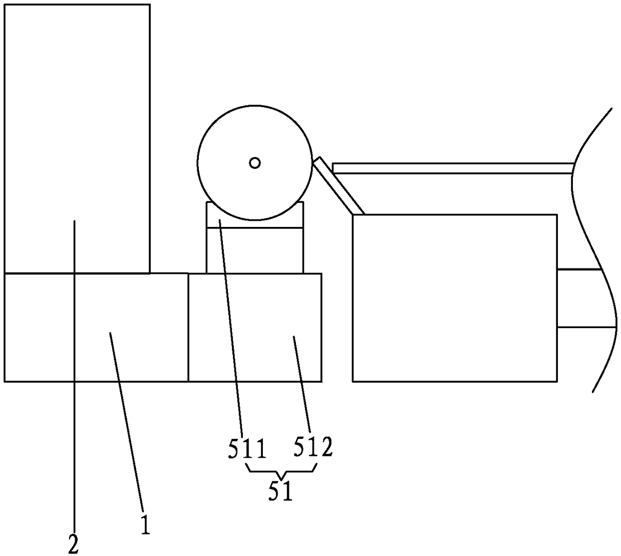
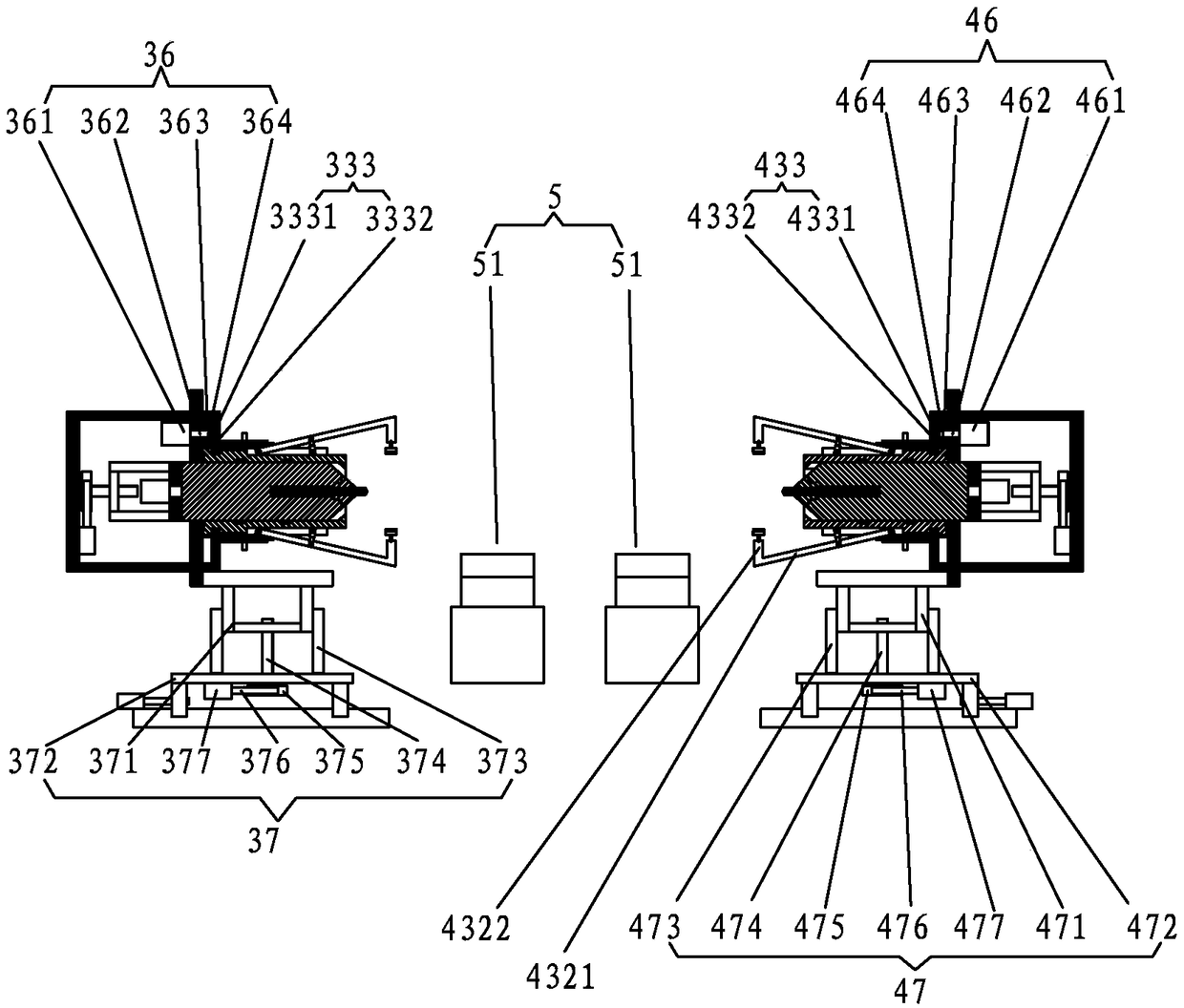
[0049] A kind of automatic high-quality rotary cutting device of the present invention, as Figure 1 to Figure 9 As shown, it includes a frame 1, a rotary cutting mechanism 2 and a clamping shaft arranged on the frame 1; the clamping shaft includes a first clamping part 3 at one end of the log, and a second clamping part 4 at the other end of the log ; Both the first clamping part 3 and the second clamping part 4 have a proximal end facing the direction of the log and a distal end facing the opposite direction; also include an initial support column 5 arranged under the log;

[0050] The first clamping part 3 includes a first main base plate 31 perpendicular to the log, a first positioning shaft mechanism passing through the first main base plate 31, and a first positioning sleeve mechanism sleeved outside the first positioning shaft...


PUM


Abstract

The invention relates to an automatic high quality rotary cutting device. In a rotary cutting process, a first lifting driving device drives a first lifting rack to lift along a first guiding frame till the center of a first positioning cutter knife and the center of a log are substantially located at a same height. A user operates a first operating handle to push a first sleeve main body to movetoward the direction of the log along a thread; the first sleeve main body applies an inward pressure to a first positioning arm through a first leaning sleeve; the first positioning arm clamps the log through a pair of first leaning tongs; and finally, the log is clamped all around by means of the leaning tongs of three positioning arms. A first advancing and retreating motor drives a first advancing and retreating worm wheel to rotate through a first advancing and retreating worm; the first advancing and retreating worm wheel drives a first shaft main body to slide toward the direction of the log through a first advancing and retreating screw; a first blade is in leaning contact with the log and cuts the log rotatably to form a groove corresponding to a first cone-shaped head to be in leaning contact with a groove formed by rotatably cutting a first end cover automatically, so that an effect of automatic centering is achieved.

Description

[0001] The patent application of this invention is a divisional application of Chinese patent application number 201810312938.5. The original application number is 201810312938.5, and the application date is April 09, 2018. The name of the invention is a high-efficiency automatic centering rotary cutting machine. technical field [0002] The invention relates to the mechanical field, in particular to an automatic high-quality rotary cutting device. Background technique [0003] At present, in the field of material cutting, the existing high-precision rotary cutting machines on the market are generally large in size and complex in structure. Before using the machine, the log needs to be centered. If the centering is not accurate, intermittent veneers will be unscrewed when the rotary cutting is started. Belt or narrow veneer. The more broken veneers or narrow veneers, the more good sapwood veneers are lost, which is not conducive to continuous production. [0004] The prior ...

Claims


Application Information

Patent Timeline
Patent Type & Authority Applications(China)
IPC IPC(8): B27L5/02
CPCB27L5/02
Inventor 黄泽辉
Owner 漳州市炯辉机械有限公司
Why Eureka
Eureka Blog
Learn More