Take-up lever device, link mechanism and production process of link mechanism

A connecting rod mechanism and production process technology, applied in the field of thread take-up rods, can solve problems such as low precision, low strength, and high noise, and achieve the effect of high combination accuracy, high strength, and low noise

Pending Publication Date: 2020-05-05
浙江博盟精工轴承有限公司
View PDF1 Cites 0 Cited by
  • Summary
  • Abstract
  • Description
  • Claims
  • Application Information

AI Technical Summary

Problems solved by technology

[0004] Aiming at the shortcomings of low precision, low strength and high noise in the assembled shaft body and bearing in the prior art, the invention provides a thread take-up device, a connecting rod mechanism and a production process of the connecting rod mechanism

Method used


Image

  • Take-up lever device, link mechanism and production process of link mechanism
  • Take-up lever device, link mechanism and production process of link mechanism
  • Take-up lever device, link mechanism and production process of link mechanism

Examples


Embodiment 1

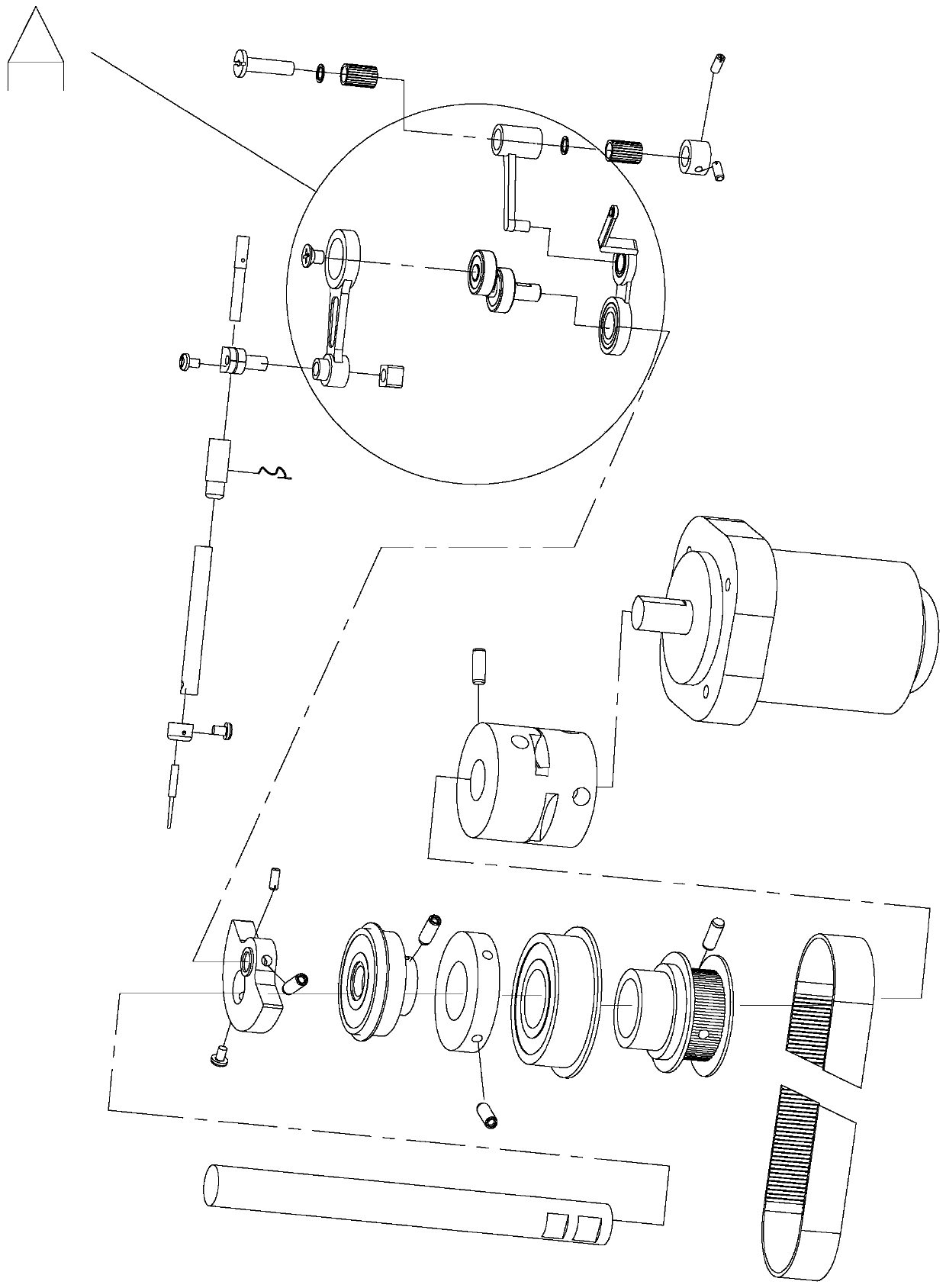
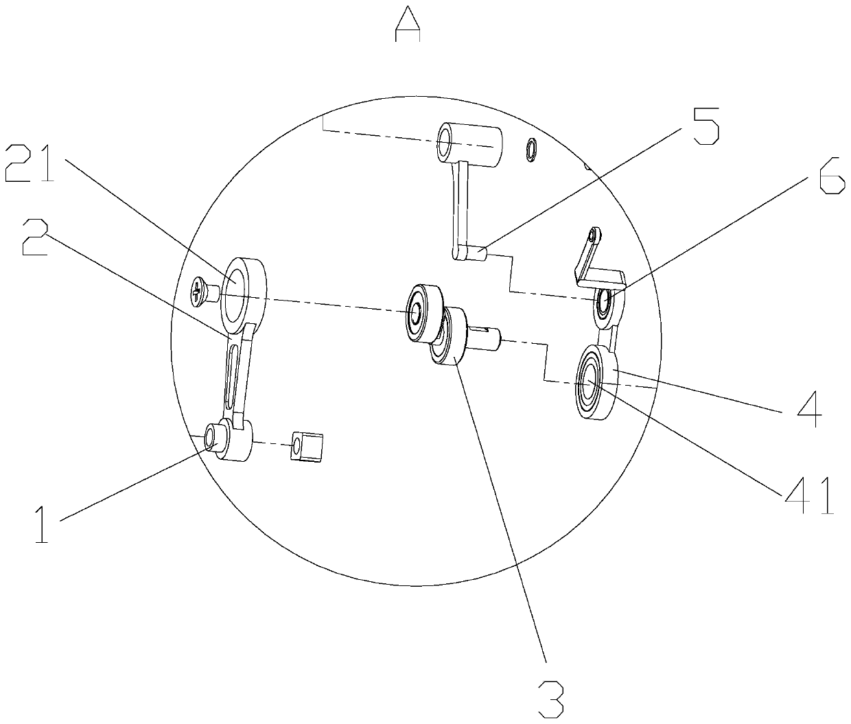
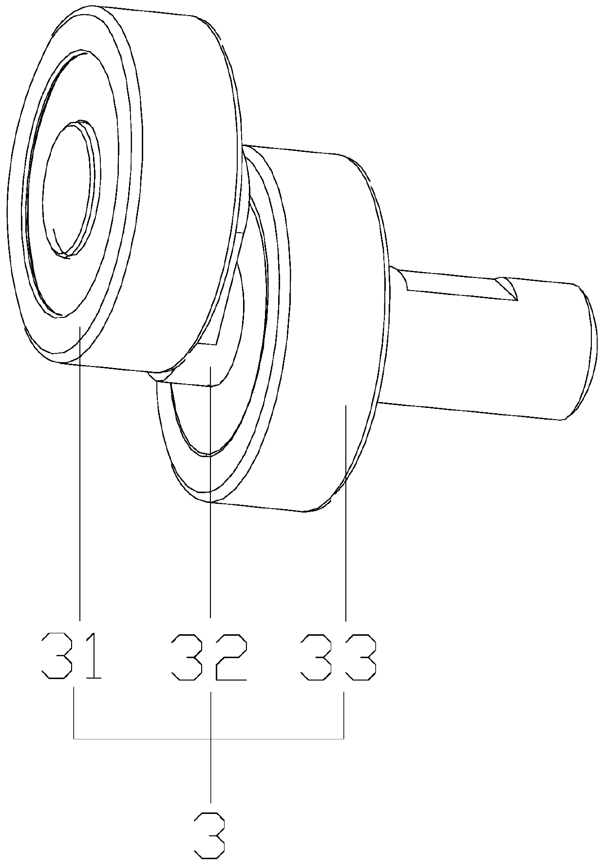
[0034] A link mechanism, as shown in the figure, includes a rolling assembly 3. The rolling assembly 3 includes a first rolling assembly 31, a special-shaped shaft 32 and a second rolling assembly 33. The first rolling assembly 31 passes through the special-shaped shaft 32 and the second rolling assembly. 33 connection, the special-shaped shaft 32 includes a first shaft body 321, a connecting block 323 and a second shaft body 322, the first shaft body 321 is connected with the second shaft body 322 through the connecting block 323, the first shaft body 321 and the second shaft body The axis lines of 322 are parallel and not collinear, the first shaft body 321, the connecting block 323 and the second shaft body 322 are in a Z shape, the first shaft body 321 is provided with a first channel 3211, and the first channel body 3211 A first ball 314 is provided, a second channel 3221 is provided on the second shaft body 322 , and a second ball 335 is provided on the second channel 322...

Embodiment 2

[0043] A thread take-up lever device, as shown in the figure, includes the linkage mechanism described in Embodiment 1.

Embodiment 3

[0045] A production process of a link mechanism, comprising the following steps:

[0046] (1) Dig out a first channel 3211 on the first shaft body 321, and put a first inner seal 315 in the first inner mounting place 3212 on the first shaft body 321;

[0047] (2) Insert the first outer ring 311 on the outer circumference of the first shaft body 321, so that the first ball 314 can enter the first channel 3211 of the first shaft body 321 and the channel of the first outer ring 311;

[0048] (3) Snap the first cage 313 onto the first ball 314, so that the first cage 313 is located between the first shaft body 321 and the first outer ring 311;

[0049] (4) Inject grease in the direction of the first outer seal 313, put the first outer seal 312 into the first outer mounting part 3213 on the first shaft body 321, cover the first outer seal 313, and use tools to The first inner seal 315 is installed into the first inner mounting place 3212;

[0050] (5) Dig out a second channel 322...


PUM


Abstract

The invention relates to the field of take-up levers and discloses a take-up lever device, a link mechanism and a production process of the link mechanism. The take-up lever device comprises a rollingcomponent, wherein the rolling component comprises a first rolling component part, a special-shaped shaft and a second rolling component part, the first rolling component part is connected with the second rolling component part through the special-shaped shaft, the special-shaped shaft comprises a first shaft body, a connecting block and a second shaft body, the first shaft body is connected withthe second shaft body through the connecting block, the first shaft body is provided with a first channel, a first ball is arranged on the first channel, the second shaft body is provided with a second channel, and a second ball is arranged on the second channel. According to the take-up lever device, the shaft bodies and bearing components are rearranged, so that the spatial size of the rollingcomponent is optimized, and the rolling component has the advantages of high combination precision, high strength and low noise; and moreover, the rolling component has better rotating flexibility.

Description

technical field [0001] The invention relates to the field of thread take-up levers, in particular to a thread take-up lever device, a link mechanism and a production process of the link mechanism. Background technique [0002] The thread take-up lever device is a relatively important part in the sewing machine. The invention patent of application number CN201810624291.X discloses a thread take-up lever structure of the sewing machine, which includes the thread take-up lever body of the sewing machine. The holes are slotted holes. Both ends of the threading hole are arc-shaped; the threading hole is an oval long slotted hole. The above-mentioned patent makes the thread passing resistance of the hooking mechanism small, and the amount of thread feeding and the pulling force of the upper thread remain stable when the thread take-up lever moves to different positions, so that the tension of the suture thread is stable, and the stitches during sewing of clothes are stable. [0...

Claims


Application Information

Patent Timeline
Patent Type & Authority Applications(China)
IPC IPC(8): D05B49/00
CPCD05B49/00
Inventor 王训武
Owner 浙江博盟精工轴承有限公司
Why Eureka
Try Eureka