Speed-controlling spraying device for sealant for construction engineering

A technology of construction engineering and spraying equipment, which is applied in the direction of construction, building components, building structures, etc., can solve the problems of inconvenient use, waste, too fast spraying flow rate, etc., and achieve the effect of increasing the spraying force and facilitating cleaning

Inactive Publication Date: 2020-05-05
深圳市河图建设项目管理有限公司
View PDF1 Cites 1 Cited by
  • Summary
  • Abstract
  • Description
  • Claims
  • Application Information

AI Technical Summary

Problems solved by technology

[0004] Ordinary devices cannot adjust the direction of the nozzle, and it is inconvenient to use in some corner gaps. At the same time, the flow rate of the sprayed sealant cannot be accurately controlled, which may easily cause the spraying flow rate to be too fast and cause waste.

Method used


Image

  • Speed-controlling spraying device for sealant for construction engineering
  • Speed-controlling spraying device for sealant for construction engineering
  • Speed-controlling spraying device for sealant for construction engineering

Examples


Embodiment 1

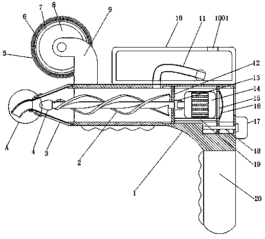
[0030] refer to Figure 1-3, a speed-controlled spraying device for sealant used in construction, comprising a main body 1, the top of the main body 1 is provided with a material storage box 10, the middle part of the main body 1 is provided with a first through hole, and the main body 1 is provided with a screw at the first through hole. Rod 2, one end of the screw rod 2 is welded with a moving body 4, the other end of the screw rod 2 is welded with a fixed sleeve 13, the main body 1 is provided with a fixed plate 19 at the bottom inner wall of the first through hole, and the top of the fixed plate 19 passes through Bolts are fixedly connected with a first motor 14, the output shaft of the first motor 14 is connected with the fixed sleeve 13 by a key, one side of the fixed plate 19 is welded with a moving plate 15, and one side of the moving plate 15 is provided with a threaded through hole, and the moving plate 15. A threaded rod 18 is provided at the threaded through hole. ...

Embodiment 2

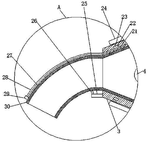
[0042] refer to Figure 4-5 , a speed-controlling spraying device for sealant used in construction projects. Compared with Embodiment 1, this embodiment, in order to increase the practicability of the device, facilitate the bending of the leather tube 30, and avoid wrinkles when the leather tube 30 is bent, the fixing body 26 A third elastic piece 38 is welded on one side, and the top of the third elastic piece 38 is bonded to the leather tube 30. When the leather tube 30 bends, the leather tube 30 will bend along the third elastic piece 38 without wrinkling, which can effectively avoid Bending and wrinkling of the hose affect the ejection of the sealant.

[0043] When in use, the threaded sleeve 22 is rotated by rotating the rotating ring 24, and the threaded sleeve 22 drives the moving piece 21 to move inside the first chute through the thread, and the moving piece 21 pushes the second elastic piece 28 to move, and the other end of the second elastic piece 28 Push the fixin...


PUM


Abstract

The invention belongs to the technical field of construction engineering devices, particularly relates to a speed-controlling spraying device for a sealant for construction engineering, and solves theproblems that the direction of a spray head cannot be adjusted and the flow rate cannot be accurately controlled when the sealant is used. The invention adopts following scheme that the speed-controlling spraying device comprises a main body; a storage box is arranged at the top end of the main body; a first through hole is formed in the middle of the main body; a spiral rod is arranged at firstthrough hole in the main body; a moving body is welded to one end of the spiral rod; and a fixing sleeve is welded to the other end of the spiral rod. A threaded sleeve rotates to push a second elastic sheet to move, and the other end of the second elastic sheet pushes a fixed block to bend a first elastic sheet and a leather tube downwards, so that the direction of the leather tube can be arbitrarily controlled; and a knob enables a threaded rod to drive a moving plate to move, and the moving plate enables the moving body to change the size of the aperture of one side of a rotating body, so that the flow rate of the sealant is controlled conveniently, and at the same time, the spray strength can be improved, and building gaps can be filled with the sealant well.

Description

technical field [0001] The invention relates to the technical field of construction engineering equipment, in particular to a speed-controlled spraying device for sealant used in construction engineering. Background technique [0002] In construction projects, sealant is a commonly used gap filling material. During decoration, the gap is usually filled with a sealant gun, so that the gap between the wall or ceiling is filled, so as to avoid affecting the actual use. . [0003] After searching, the Chinese Patent Publication No. is CN108343219B, which discloses a sealant spraying device for construction engineering. The spraying device is fixed on the fifth bracket, the lower end of the first bracket is an L-shaped bracket, and the controller fixed above the lower part of the first bracket, the hand-held bracket is installed on the upper end of the first bracket, three of the first wheels are respectively fixed in pairs of first brackets, and the second wheels are installed ...

Claims


Application Information

Patent Timeline
Patent Type & Authority Applications(China)
IPC IPC(8): E04B1/682
CPCE04B1/68E04B1/6801
Inventor 李超柳晓云柳泽滨张世杰陈俊君刘钦杰
Owner 深圳市河图建设项目管理有限公司
Why Eureka
Try Eureka