Display panel splitting device

A technology of display panels and lobes, applied in nonlinear optics, instruments, optics, etc., can solve problems such as damage to display devices, difficulty in controlling the R angle, etc., and achieve the effect of avoiding uneven force

Pending Publication Date: 2020-05-05
SHENZHEN CHINA STAR OPTOELECTRONICS TECH CO LTD
View PDF9 Cites 1 Cited by
  • Summary
  • Abstract
  • Description
  • Claims
  • Application Information

AI Technical Summary

Problems solved by technology

[0004] The present application provides a display panel cracking device, which is used to solve the technical problem that the existing method for forming the R angle of the display device is difficult to control, resulting in damage to the display device

Method used


Image

  • Display panel splitting device
  • Display panel splitting device
  • Display panel splitting device

Examples


Embodiment Construction

[0025] The technical solutions in the embodiments of the present application will be clearly and completely described below in conjunction with the drawings in the embodiments of the present application. Apparently, the described embodiments are only some of the embodiments of this application, not all of them. Based on the embodiments in this application, all other embodiments obtained by those skilled in the art without making creative efforts belong to the scope of protection of this application.

[0026] In the description of the present application, it should be understood that the terms "center", "longitudinal", "transverse", "length", "width", "thickness", "upper", "lower", "front", " Orientation indicated by rear, left, right, vertical, horizontal, top, bottom, inside, outside, clockwise, counterclockwise, etc. The positional relationship is based on the orientation or positional relationship shown in the drawings, which is only for the convenience of describing the a...


PUM


Abstract

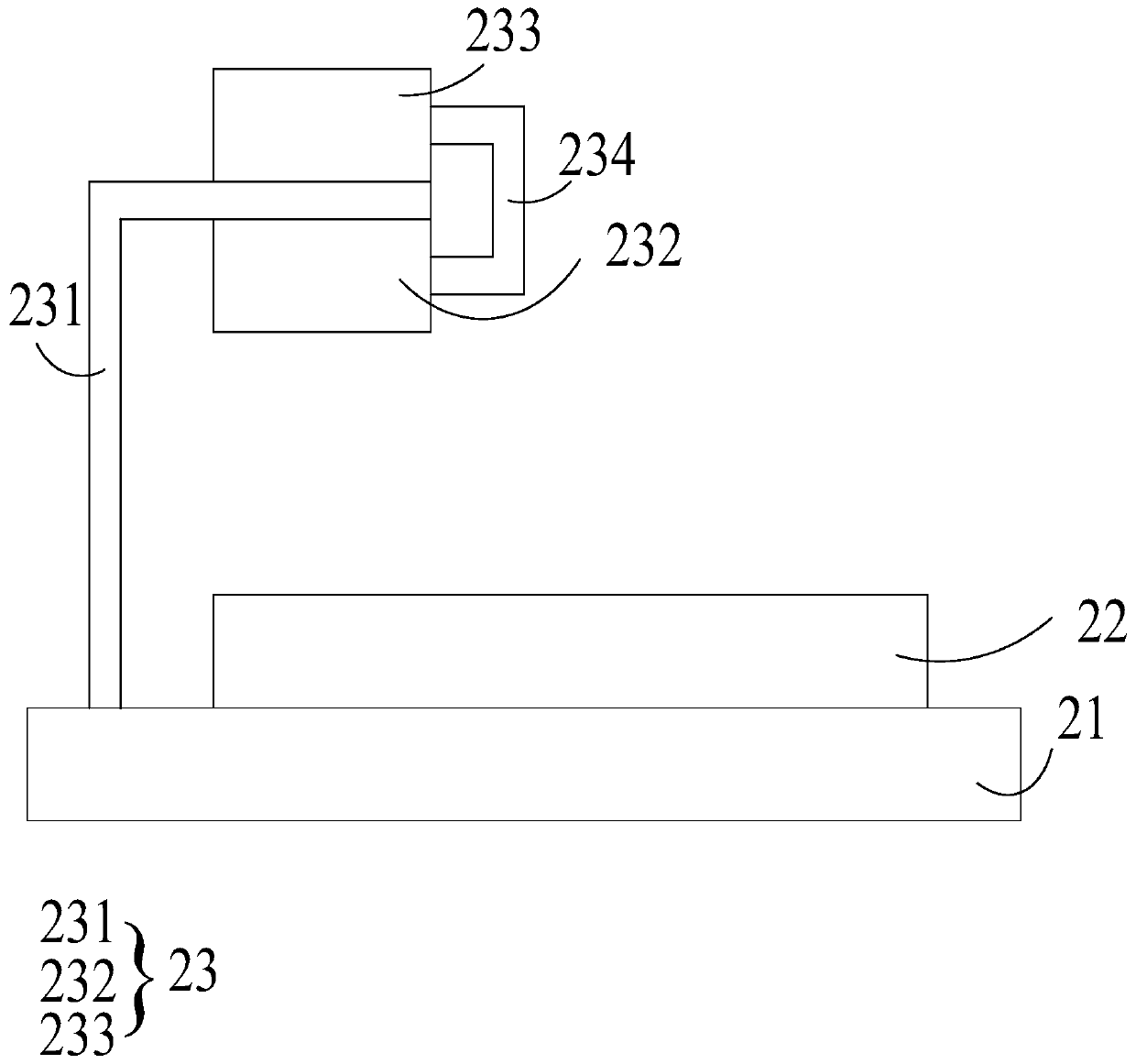
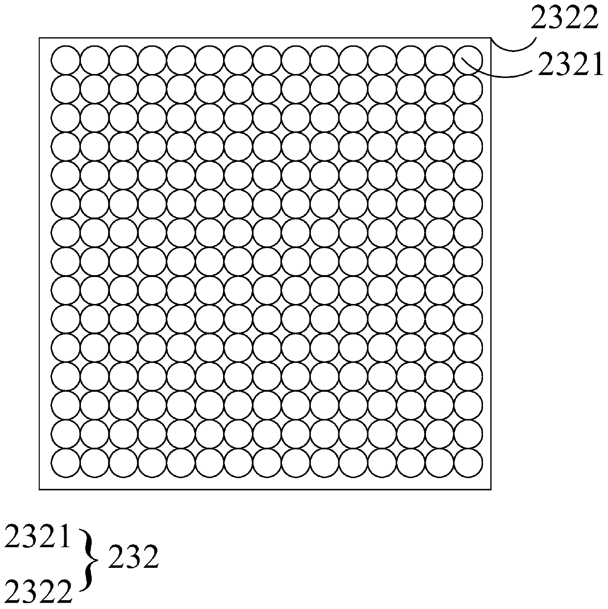
The invention provides a display panel splitting device. The display panel splitting device comprises a machine table and a splitting component. The machine table is used for bearing a display panel,the splitting component comprises a jetting assembly and a bearing assembly, the bearing assembly is arranged above the machine table, the jetting assembly is arranged between the bearing assembly andthe machine table assembly and attached to the bearing assembly, and the jetting assembly is used for jetting fluid to the display panel; fluid is sprayed to a display panel from the upper part of the display panel by adopting the splitting component, and the display panel is split by using the fluid; the flow of the fluid is controllable, and the arrangement position of the jetting assembly is controllable, so that the stress of the display panel is controllable when the display panel is split, the situation that the stress of the display panel is uneven when the display panel is split is avoided, and the technical problems that an existing method for forming an R angle of the display device is difficult to control and the display device is damaged are solved.

Description

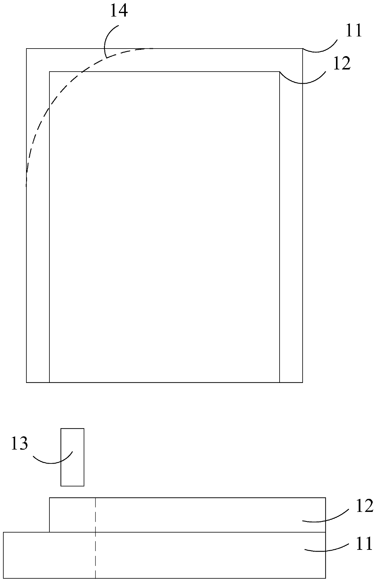
technical field [0001] The present application relates to the field of display technology, in particular to a splitting device for a display panel. Background technique [0002] In order to realize the aesthetic appearance of the existing display device, the edge of the display device is designed as an R angle. During the formation of the R angle, such as figure 1 As shown, the edge of the display device will be tapped to achieve the purpose of forming an R angle, but during the tapping process, since the tap is aimed at a point or a small area, the force on the display device will be uneven. As a result, there is a defect in the R angle formed by the lobes, and because the knocking force is difficult to control, there will be a risk of the display device being shattered, resulting in damage to the display device and making it unusable. [0003] Therefore, the existing method for forming the R-angle of the display device has the technical problem that it is difficult to con...

Claims


Application Information

Patent Timeline
Patent Type & Authority Applications(China)
IPC IPC(8): G02F1/13
CPCG02F1/1303
Inventor 迟茂强
Owner SHENZHEN CHINA STAR OPTOELECTRONICS TECH CO LTD
Why Eureka
Try Eureka