Ring rolling machine controlled by core roll rotation drive

A technology of rotary drive and ring rolling machine, which is applied in the field of ring rolling machine, which can solve the problems of uneven distribution of internal grains and hard phases, poor precision and quality retention, and short life of ring products, so as to achieve quality and precision maintenance Good performance, good for full circle, low cost effect

Active Publication Date: 2018-06-26
WUHAN UNIV OF TECH
View PDF7 Cites 0 Cited by
  • Summary
  • Abstract
  • Description
  • Claims
  • Application Information

AI Technical Summary

Problems solved by technology

[0005] Aiming at the problems that the internal structure of the existing ring rolling machine causes uneven distribution of internal crystal grains and hard phases due to severe uneven strain distribution, resulting in short service life, poor precision and quality retention of ring products, the purpose of the present invention is to Provided is a ring rolling machine controlled by core roll rotation drive, which increases the active control of core roll rotation on the basis of ordinary ring rolling machines, and adopts actively rotating drive rolls and actively rotating core rolls to form a mold that is beneficial to plasticity Stressed state of deformation uniformity, low cost, easy to realize, and can greatly improve the internal structure uniformity of rolled rings

Method used


Image

  • Ring rolling machine controlled by core roll rotation drive
  • Ring rolling machine controlled by core roll rotation drive
  • Ring rolling machine controlled by core roll rotation drive

Examples


Embodiment Construction

[0021] The present invention will be further described below in conjunction with the accompanying drawings and embodiments.

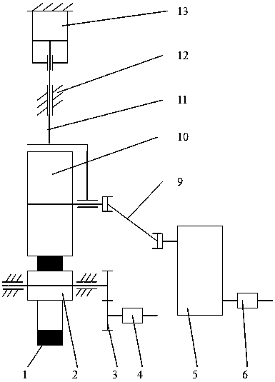
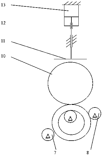
[0022] Such as figure 1 and figure 2 As shown, in this embodiment, a ring rolling machine controlled by the rotation of the core roll includes a body 12 provided with rails, a slider 11 that cooperates with the rails on the body 12, and a hydraulic cylinder that drives the slider 11 to move along the rails. 13. The core roller 2 set on the fuselage 12 through the bearing, the driving roller 10 rotatably fixed on the slider 11, the measuring roller 7, the guide roller 8, the hydraulic motor 4, the gear pair 3, the motor 6, and the reducer 5 and a universal joint coupling 9; the output shaft of the hydraulic motor 4 is connected to the core roller 2 through a gear pair 3, and the output shaft of the motor 6 is connected to the drive shaft through a reducer 5 and a universal joint coupling 9 The rollers 10 are axially connected, the driving roller 10 is...


PUM


Abstract

The invention relates to a ring rolling mill capable of driving and controlling rotation of a core roller. The ring rolling mill comprises the core roller and a driving roller which can initiatively rotate and conduct linear feeding. The ring rolling mill is characterized in that the core roller can initiatively rotates and is controllable in speed, and the core roller can achieve switching of the two modes of initiative driving and follow moving in the working process. According to the ring rolling mill, the driving roller initiatively rotating and driving and the core roller initiatively rotating and driving can be adopted at the same time, in the rolling process, stress of a deformation area of a rolled ring part is controllable by controlling the rotating speed of the core roller, matched friction force can be generated on the inner and outer contact surfaces of the rolled ring part, so that uniform radial deformation is generated, and thus the uniformity of the internal texture of the rolled ring part is greatly improved; the ring rolling mill is low in cost, easy to achieve and suitable for production of ring-shaped parts which are high in material microstructure uniformity requirement, good in quality and precision retainability and long in service life.

Description

technical field [0001] The invention belongs to the field of ring rolling machines, and in particular relates to a ring rolling machine controlled by core roll rotation drive. Background technique [0002] The ring rolling machine commonly used in my country has a simple structure. The driving roller is driven to rotate through the motor and the reduction box, and the driving roller is driven to move in a straight line through hydraulic pressure or air pressure. When the pass is formed with the core roll, the ring blank will be deformed with a reduced thickness and a larger diameter. This ring rolling machine has a simple structure, easy manufacture, cheap price, and wide application, and can produce ordinary ring products conveniently and quickly. [0003] In the existing ring binding machine, the core roll is a follower during the rolling process, and the core roll will rotate due to friction with the inner surface of the ring, so the rotation speed of the core roll has a l...

Claims


Application Information

Patent Timeline
Patent Type & Authority Patents(China)
IPC IPC(8): B21H1/06
CPCB21H1/06
Inventor 兰箭华林钱东升毛华杰冯绍贵
Owner WUHAN UNIV OF TECH
Why Eureka
Try Eureka