Electromagnetic suspension energy recovery type supporting braking system

A technology of energy recovery and braking system, which is applied in the direction of electric components, electrical components, electromechanical devices, etc., can solve the problems of volume and energy saving limitations, non-integration, poor versatility, etc., and achieve the effect of optimizing volume and good space structure

Pending Publication Date: 2017-05-10
GUILIN UNIV OF AEROSPACE TECH
View PDF7 Cites 0 Cited by
  • Summary
  • Abstract
  • Description
  • Claims
  • Application Information

AI Technical Summary

Problems solved by technology

[0002] The current motor equipment still uses traditional mechanical contact bearings. In traditional motors, due to technical and structural limitations, the output speed of the motor reaches the level of 10,000 revolutions in civil and most industries, medicine, scientific research and military fields. , the output torque did not reach a relatively high value
With the support of new technology, new structure and better machining accuracy, the speed of new motor equipment is gradually exceeding the traditional category. Traditional bearings are one of the main factors that limit the further speed-up of electromagnetic motors, and some can withstand higher Hydrostatic bearings with high speed and torque have poor versatility due to their delicate environmental requirements and volume problems, and they are still far from enough for new motors
Moreover, because in the traditional design, the bearing and the braking system are not integrated, and the braking is performed by consuming energy and converting kinetic energy into heat energy, there are certain limitations in volume and energy saving

Method used


Image

  • Electromagnetic suspension energy recovery type supporting braking system

Examples


Embodiment

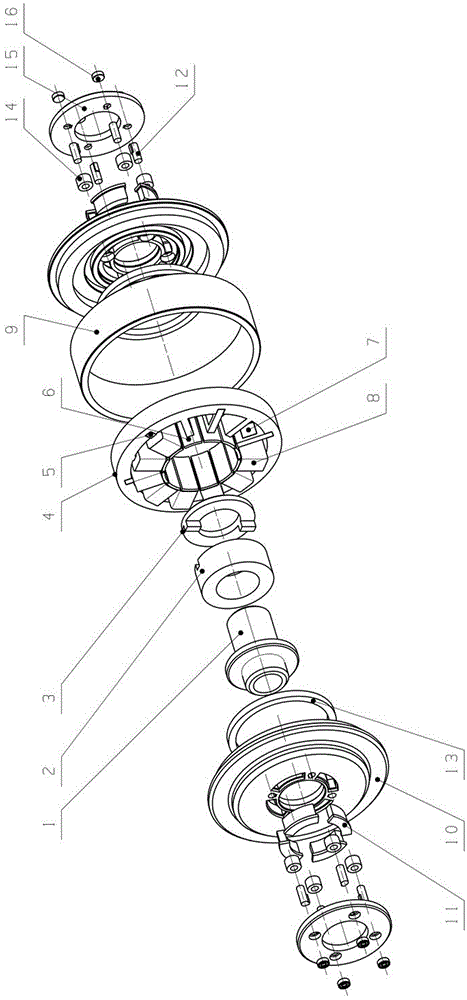
[0014] refer to figure 1 , an electromagnetic levitation energy recovery support brake system, which consists of an inner shaft sleeve 1, a silicon steel ring 2, a silicon steel sleeve 3, an iron core 4, a magnetic steel insert 5, a steel insert 6, a magnetic block 7, a coil 8, and an outer Shaft sleeve 9, axial sleeve disc 10, axial magnetic block 11, axial iron core 12, axial silicon steel ring 13, axial coil 14, brake sleeve disc 15 and brake electromagnet 16,

[0015] The left end of the inner shaft sleeve 1 is connected to the axial sleeve disc 10 through the axial silicon steel ring 13, and the axial magnetic block 11 is arranged on the axial sleeve disc 10; the right end of the inner shaft sleeve 1 is connected to the silicon steel ring 2, and the silicon steel ring 2 passes through the silicon steel The sleeve 3 is connected with the iron core 4, and the magnetic steel inserts 5, steel inserts 6, magnetic blocks 7 and coils 8 are evenly and alternately arranged in the ...


PUM


Abstract

The invention discloses an electromagnetic suspension energy recovery type supporting braking system which comprises an outer sleeve, an inner sleeve, a silicon steel ring and an iron core, wherein the inner sleeve, the silicon steel ring and the iron core are arranged in the outer sleeve. One end of the inner sleeve is connected with an axial magnetic block through an axial sleeve disk, and the other end is connected with the silicon steel ring. The silicon steel ring is connected with the iron core. The iron core is internally provided with magnetic steel insertion blocks, steel insertion sheets, steel insertion sheets, magnetic blocks and coils, wherein the magnetic steel insertion blocks, the steel insertion sheets, the magnetic blocks and the coils are uniformly and alternatively arranged. The other end of the iron core is connected with a braking sleeve and a braking electromagnet. The electromagnetic suspension energy recovery type supporting braking system is beneficial in that a no-friction support can be supplied; through motor performance, an auxiliary bearing can be abandoned in power-off operation; braking and energy recovery are integrated; size is optimized for realizing a better spatial structure; furthermore better energy saving effect is realized; controllable force bearing magnitude and high versatility are realized; and the electromagnetic suspension energy recovery type supporting braking system can be used in an adverse environment.

Description

technical field [0001] The invention relates to magnetic levitation technology and electromagnetic brake technology, in particular to an electromagnetic levitation energy recovery support brake system. Background technique [0002] The current motor equipment still uses traditional mechanical contact bearings. In traditional motors, due to technical and structural limitations, the output speed of the motor reaches the level of 10,000 revolutions in civil and most industries, medicine, scientific research and military fields. , the output torque did not reach a relatively high value. With the support of new technology, new structure and better machining accuracy, the speed of new motor equipment is gradually exceeding the traditional category. Traditional bearings are one of the main factors that limit the further speed increase of electromagnetic motors, and some can withstand higher speeds. Hydrostatic bearings with high speed and torque have poor versatility due to their ...

Claims


Application Information

Patent Timeline
Patent Type & Authority Applications(China)
IPC IPC(8): H02K7/102H02N15/00
CPCH02K7/1025H02N15/00
Inventor 张栋梁何雨桓张迪
Owner GUILIN UNIV OF AEROSPACE TECH
Why Eureka
Try Eureka