
A heat sink shared by multiple chips and a circuit board provided with the heat sink

A circuit board and heat sink technology, applied in the field of communication, can solve problems such as limited improvement of heat dissipation capacity, creep of chip solder joints, and limited heat dissipation area, so as to improve heat dissipation capacity, avoid solder joint creep, and controllable force on chips Effect

Active Publication Date: 2015-09-30
HUAWEI TECH CO LTD
View PDF5 Cites 0 Cited by
  • Summary
  • Abstract
  • Description
  • Claims
  • Application Information

AI Technical Summary

Problems solved by technology

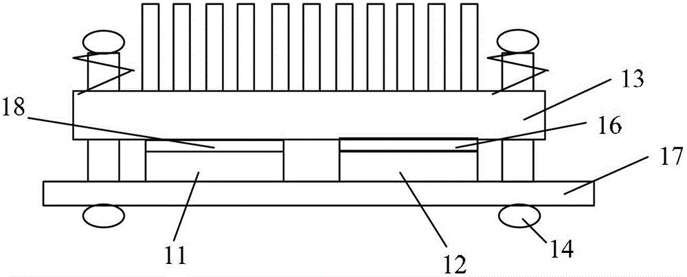
[0004] The above-mentioned existing technology expands the heat dissipation area, but in the process of realizing the embodiment of the present invention, the inventor found that the existing technology can only use a common heat sink for some chips of the same type, so the heat dissipation area is limited and the heat dissipation capacity is limited; It is difficult to share the heat sink between different types of chips. By increasing the thickness of the heat conduction layer to fill the height difference between the chip and the heat sink, there is a risk of uncontrollable force on the chip or creep of the solder joint on the circuit board.

Method used


Image

  • A heat sink shared by multiple chips and a circuit board provided with the heat sink
  • A heat sink shared by multiple chips and a circuit board provided with the heat sink
  • A heat sink shared by multiple chips and a circuit board provided with the heat sink

Examples


Embodiment Construction

[0016] In each embodiment of the present invention, the lower surface of the heat sink substrate, that is, the side closest to the chip is provided with a plurality of bosses. For chips with a small chip height tolerance on the circuit board, according to the difference in the height of the bosses, Match chips of different heights; and add limit brackets on the radiator to provide support for the radiator to be placed on the circuit board, thereby controlling the pressure on the chip and avoiding excessive force on the chip and causing it to be placed on the circuit board. The creep of the upper solder joints is realized, and multiple chips share a heat sink to increase the heat dissipation area.

[0017] figure 2 It is a structural schematic diagram of an embodiment of the radiator of the present invention. Such as figure 2 As shown, the heat sink shared by multiple chips includes: a base plate 221, and a plurality of heat dissipation fins 233 are arranged on the upper su...


PUM


Abstract

The embodiment of the invention provides a heat radiator shared by multiple chips and a circuit board provided with the heat radiator. The heat radiator comprises a base plate, wherein the upper surface of the base plate is provided with multiple radiating fins; the lower surface of the base plate is provided with at least one boss mutually contacted with the upper surface of a first chip on the circuit board; and the edge of the base plate is provided with a limiting bracket used for supporting the base plate on the circuit board. The invention further provides a circuit board provided with the heat radiator. The boss is arranged on the base plate of the heat radiator and the limiting bracket is arranged on the base plate, so that the heat radiating area can be expanded to the whole circuit board and can be enlarged, and the heat-radiating capability can be enhanced; and meanwhile, multiple different types of chips can share the heat radiator, so that the stress of the chip is controllable, and the risk that the stress of the chips is overlarge, and the bonding point of the circuit board is subjected to creep deformation is solved.

Description

technical field [0001] The embodiments of the present invention relate to the technical field of communications, and in particular to a heat sink shared by multiple chips and a circuit board provided with the heat sink. Background technique [0002] With the rapid development of science and technology, the capacity of chips and boards in equipment continues to increase, and the power consumption of chips and boards is also increasing. In order to meet the requirement of heat dissipation capability, the radiator area of ​​the single board is also getting larger and larger, which already exceeds 50% of the area of ​​the single board. Even so, it still cannot meet the heat dissipation requirements. [0003] In the prior art, two chips of the same type usually use a common heat sink, wherein the height dimensions and tolerances of the two chips are consistent. figure 1 It is a structural schematic diagram of a heat sink in the prior art. Such as figure 1 As shown, at least a...

Claims


Application Information

Patent Timeline
Patent Type & Authority Patents(China)
IPC IPC(8): H01L23/367H01L23/40H05K7/20
Inventor 李忠信郭金星张良
Owner HUAWEI TECH CO LTD
Learn More