
Fault detection method, device and apparatus for distributed storage system and computer readable storage medium

A distributed storage and fault detection technology, which is applied in error detection/correction, instrumentation, electrical digital data processing, etc., can solve problems such as cluster unavailability, false alarm abnormalities, and affecting the normal use of distributed storage systems, so as to improve accuracy The effect of ensuring normal use and avoiding misjudgment of faults

Active Publication Date: 2020-05-05
LANGCHAO ELECTRONIC INFORMATION IND CO LTD
View PDF12 Cites 2 Cited by
  • Summary
  • Abstract
  • Description
  • Claims
  • Application Information

AI Technical Summary

Problems solved by technology

However, there will be a problem with this method: for example, assuming that there are two actual faulty nodes in the current distributed storage system, other nodes will report the abnormality of these two actual faulty nodes, and these two actual faulty nodes will also report all other faulty nodes. The node is abnormal; in this way, each other node is reported abnormal by at least the two actual faulty nodes, and since the number of abnormal reports of each other node exceeds the preset threshold value, the cluster management process will send all The node is set as a failed node, resulting in the unavailability of the entire cluster
In reality, the cluster may still be available with only two actual failed nodes
It can be seen that the fault detection method for the distributed storage system in the prior art, when the back-end network of the node fails, there will be false alarms, which will affect the normal use of the entire distributed storage system

Method used


Image

  • Fault detection method, device and apparatus for distributed storage system and computer readable storage medium
  • Fault detection method, device and apparatus for distributed storage system and computer readable storage medium
  • Fault detection method, device and apparatus for distributed storage system and computer readable storage medium

Examples


Embodiment Construction

[0047] The following will clearly and completely describe the technical solutions in the embodiments of the present invention with reference to the accompanying drawings in the embodiments of the present invention. Obviously, the described embodiments are only some, not all, embodiments of the present invention. Based on the embodiments of the present invention, all other embodiments obtained by persons of ordinary skill in the art without making creative efforts belong to the protection scope of the present invention.

[0048] The core of the embodiments of the present invention is to provide a fault detection method for a distributed storage system, which can improve the accuracy of fault detection for the distributed storage system and relatively guarantee the normal use of the distributed storage system; another core of the present invention is A fault detection device, equipment, and computer-readable storage medium of a distributed storage system are provided, all of whic...


PUM


Abstract

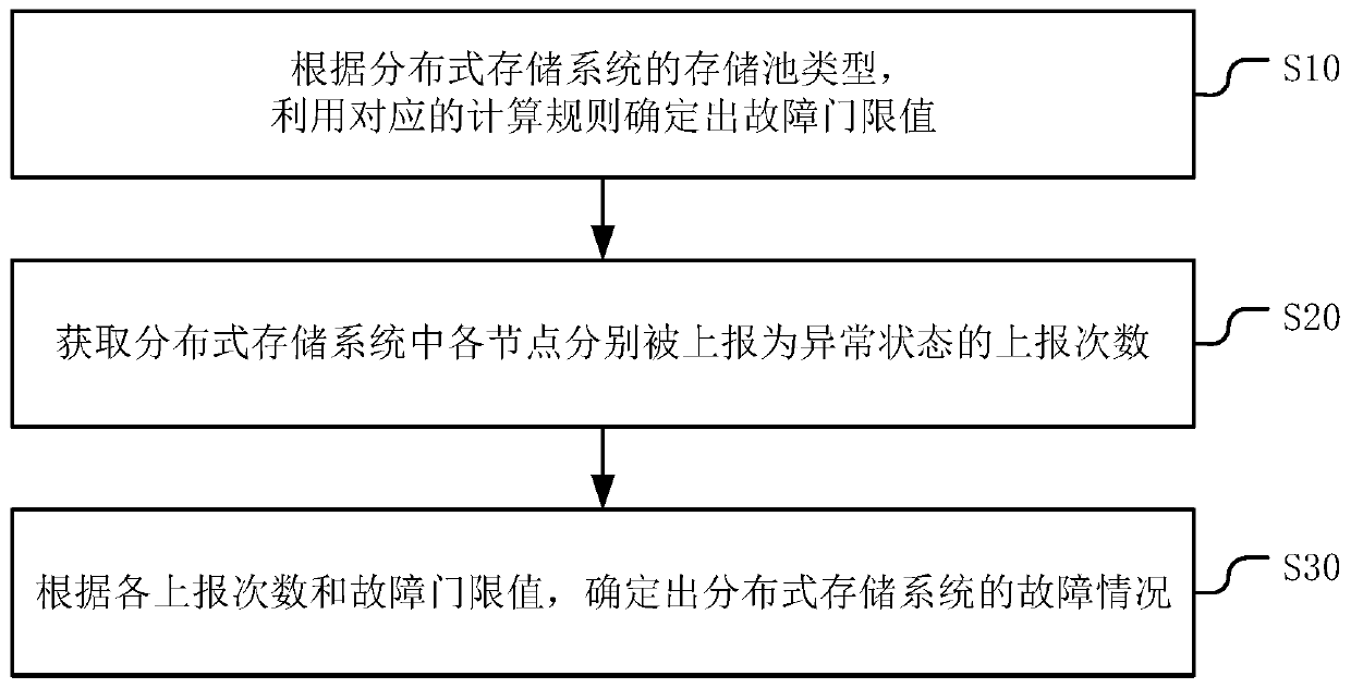
The invention discloses a fault detection method, device and apparatus for a distributed storage system and a computer readable storage medium, and the method comprises the steps: determining a faultthreshold value through a corresponding calculation rule according to the type of a storage pool of the distributed storage system; obtaining the reporting times of each node reported as an abnormal state in the distributed storage system; and determining the fault condition of the distributed storage system according to each reporting frequency and the fault threshold value. The fault threshold value is confirmed by using a corresponding calculation rule according to the type of the storage pool of the storage system. so that the fault condition of the distributed storage system is determinedaccording to each reporting frequency and the fault threshold value, fault misjudgment caused by the fact that a node with a fault in a back-end network reports other node anomalies by mistake can beavoided, the fault detection accuracy of the distributed storage system is improved, and the normal use of the whole distributed storage system is relatively guaranteed.

Description

technical field [0001] The present invention relates to the field of distributed storage systems, in particular to a fault detection method, device, equipment and computer-readable storage medium of a distributed storage system. Background technique [0002] In a distributed storage system, by setting up a daemon process (or service) on each node, it is used to provide access and monitoring to the hard disk in the storage pool; and through the communication between daemon processes (or services) between different nodes Heartbeat messages to detect whether the peer daemon process (or service) is normal. [0003] For each node, it includes the front-end network and the back-end network. The front-end network is used for customer business, and the back-end network is used for message communication and data interaction within the cluster. In order to detect the connectivity of the network, the daemon process between nodes will The network and the back-end network perform heartb...

Claims


Application Information

Patent Timeline
Patent Type & Authority Applications(China)
IPC IPC(8): G06F11/30
CPCG06F11/3034G06F11/3055G06F11/3072
Inventor 甄天桥孟祥瑞
Owner LANGCHAO ELECTRONIC INFORMATION IND CO LTD
Learn More