Detachable resistor

A technology of resistors and porcelain tubes, applied in the direction of resistors, resistor parts, circuits, etc., can solve problems such as troublesome and inconvenient to carry, and achieve the effects of easy disassembly and fixed installation, easy to carry, and simple structure

Inactive Publication Date: 2020-05-05
YONGDING XIANGYI ELECTRONICS CO LTD
View PDF0 Cites 2 Cited by
  • Summary
  • Abstract
  • Description
  • Claims
  • Application Information

AI Technical Summary

Problems solved by technology

[0002] A resistor is a current-limiting component in a circuit, and it is one of the most common and widely used electronic components. However, with the rise of precision electronics, the requirements for resistors are getting higher and higher. Not only resistors are required To have good performance, the resistor needs to be simple in structure, practical and convenient. The resistance value of the resistance element is generally related to temperature, material, length, and cross-sectional area. The physical quantity that measures the resistance affected by temperature is the temperature coefficient. Its definition It is the hundreds of times that the resistance value changes when the temperature rises by 1 °C. The main physical characteristic of the resistance is to change the electric energy into heat energy. It can also be said that it is an energy-consuming element. The internal energy is generated when the current passes through it. The resistance is in the circuit. It usually acts as a voltage divider and shunt. Traditional resistors are generally fixed, thus limiting the resistance value. When workers go out to work, they often need to carry a lot of resistors with different resistance values, which is troublesome and not easy to carry.

Method used


Image

  • Detachable resistor
  • Detachable resistor

Examples


Embodiment Construction

[0018] In order to make the technical means, creative features, goals and effects achieved by the present invention easy to understand, the present invention will be further described below in conjunction with specific embodiments.

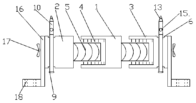
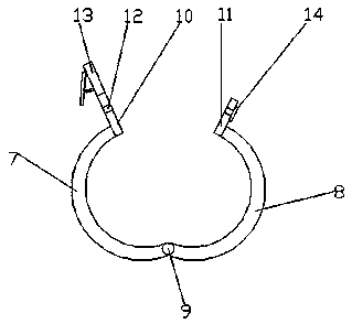
[0019] see Figure 1-2 , the present invention provides a technical solution: a detachable resistor, including a first porcelain tube 1, the left and right sides of the first porcelain tube 1 are respectively provided with a second porcelain tube 2 and a third porcelain tube 3, the The inner wall at the left end and the outer wall at the right end of the first porcelain tube 1 are provided with internal threads 4 and external threads 5 respectively, and the outer wall at the right end of the second porcelain tube 2 and the inner wall at the left end of the third porcelain tube 3 are respectively provided with external threads 5 and internal threads. 4. The left and right ends of the first porcelain tube 1 are respectively screwed to the right end ...


PUM


Abstract

The invention discloses a detachable resistor, which comprises a first porcelain tube. A second porcelain tube and a third porcelain tube are arranged at the left side and the right side of the firstporcelain tube respectively; the inner wall of the left end and the outer wall of the right end of the first porcelain tube are provided with an internal thread and an external thread respectively; the outer wall of the right end of the second porcelain tube and the inner wall of the left end of the third porcelain tube are provided with an external thread and an internal thread respectively; andthe left end and the right end of the first porcelain tube are spirally connected with the right end of the second porcelain tube and the left end of the third porcelain tube respectively. The internal thread and external thread formed in the inner wall of the left end and the outer wall of the right end of the first porcelain tube are spirally connected with external thread and internal thread formed in the outer wall of the right end of the second porcelain tube and the inner wall of the left end of the third porcelain tube, so that the resistor can be detached conveniently; meanwhile, the two groups of first porcelain tubes can be spirally connected with each other, so that the resistance value of the resistor is convenient to adjust; and the resistor is simple in structure and convenient to carry.

Description

technical field [0001] The invention relates to the technical field of resistors, in particular to a detachable resistor. Background technique [0002] A resistor is a current-limiting component in a circuit, and it is one of the most common and widely used electronic components. However, with the rise of precision electronics, the requirements for resistors are getting higher and higher. Not only resistors are required To have good performance, the resistor structure is also required to be simple, practical and convenient. The resistance value of the resistance element is generally related to temperature, material, length, and cross-sectional area. The physical quantity that measures the resistance affected by temperature is the temperature coefficient. Its definition It is the hundreds of times that the resistance value changes when the temperature rises by 1 °C. The main physical characteristic of the resistance is to change the electric energy into heat energy. It can al...

Claims


Application Information

Patent Timeline
IPC IPC(8): H01C1/022H01C1/014
CPCH01C1/014H01C1/022
Inventor 不公告发明人
Owner YONGDING XIANGYI ELECTRONICS CO LTD
Why Eureka
Try Eureka