Winding device and square power battery cell winding machine

A winding device and winding head technology, applied in circuits, electrical components, secondary batteries, etc., can solve the problems of potential safety hazards, collision of the push-closing needle unit, difficult needle winding, etc., to ensure the quality of glue sticking, prevent swaying effect

Pending Publication Date: 2020-05-05
ZHUHAI HIGRAND ELECTRONICS TECH
View PDF0 Cites 3 Cited by
  • Summary
  • Abstract
  • Description
  • Claims
  • Application Information

AI Technical Summary

Problems solved by technology

However, since the existing winding device is not equipped with a mechanism to limit the winding needle during the position switching process, and the pushing and closing needle unit and the opening and pulling unit do not rotate with the winding head, the winding needle is following During the rotation of the winding head, the winding needle is easy to move along its own axis due to vibration, so that after the winding head completes the reversing, it is difficult to accurately align and switch the actuator end of the push-close needle unit to the winding station It is difficult for the execution end of the opening and pulling unit to accurately control the needle rollin

Method used


Image

  • Winding device and square power battery cell winding machine
  • Winding device and square power battery cell winding machine
  • Winding device and square power battery cell winding machine

Examples


Embodiment Construction

[0039] Example of winding device:

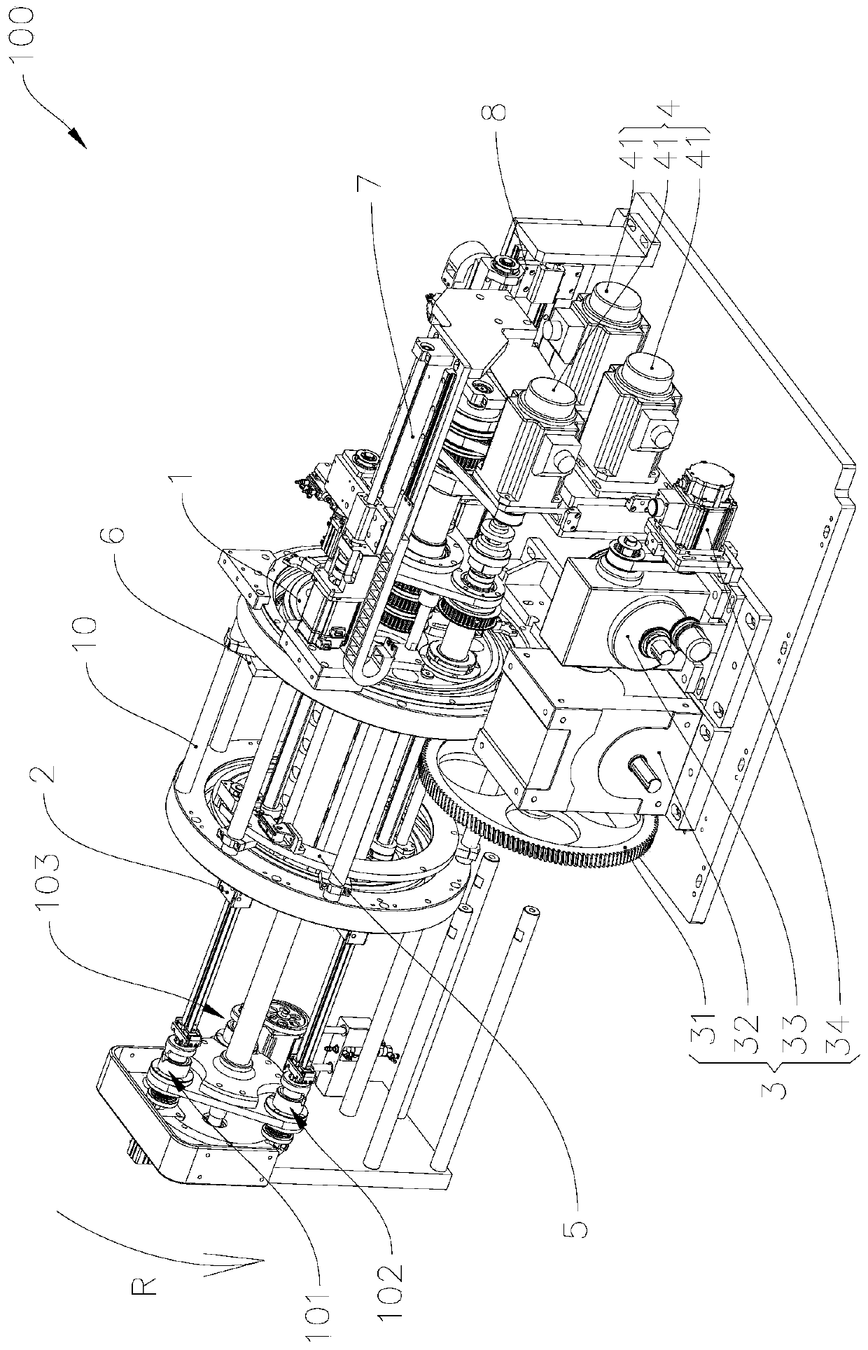
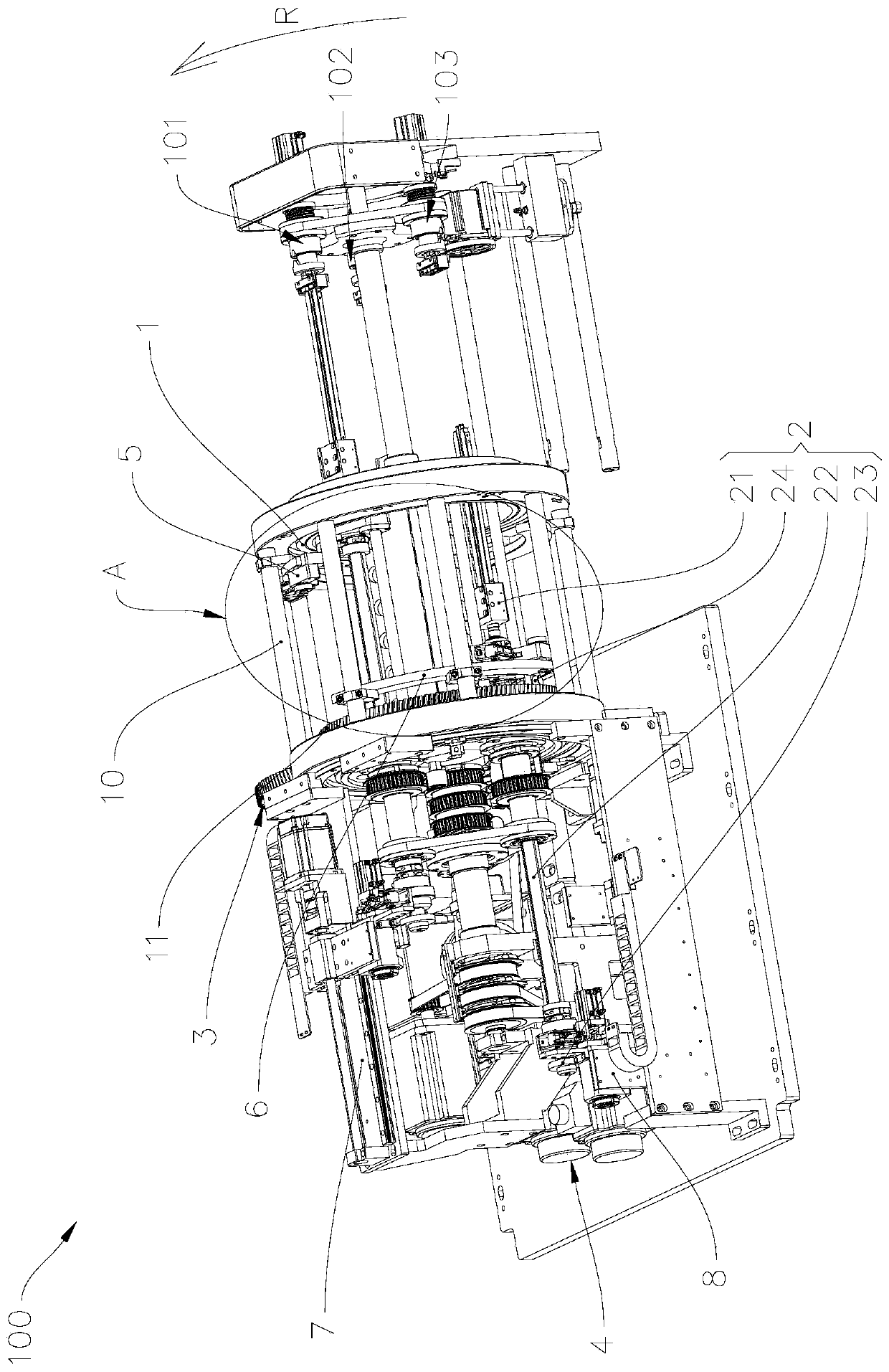
[0040] refer to Figure 1 to Figure 3 , the winding device 100 includes a frame 10, a winding head 1, a winding needle 2, a reversing unit 3, a driving unit 4, a first limit unit 5, a second limit unit 6, a push-close needle unit 7 and an open and draw needle unit 8. Wherein, the winding device 100 has a winding station 101, a gluing station 102 and a blanking station 103, and the positions of the winding station 101, the gluing station 102 and the blanking station 103 are relative to the frame 10 stable.

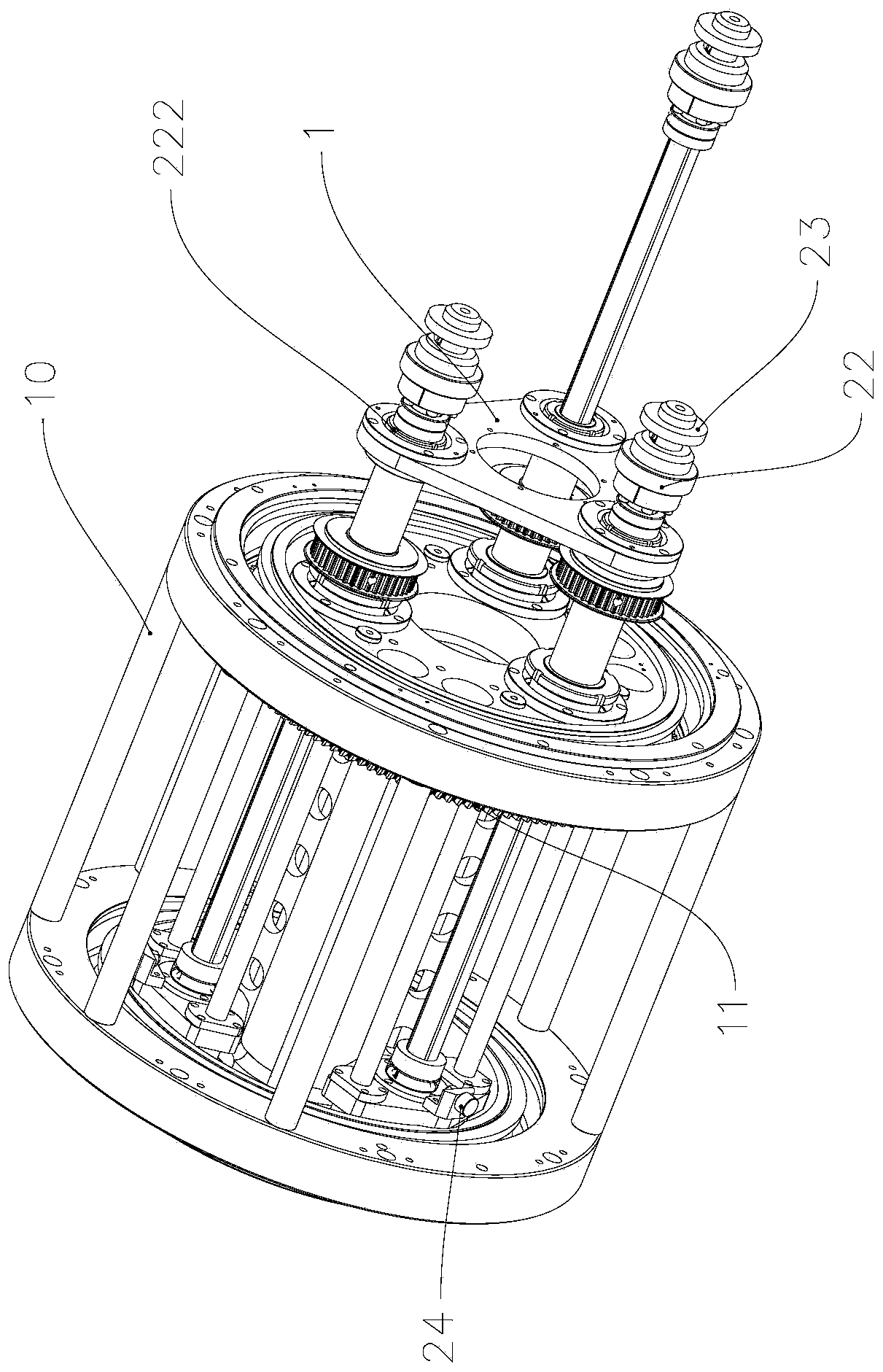
[0041] The winding head 1 is rotatably mounted on the frame 10 around its own axis, the number of winding needles 2 is three, and the three winding needles 2 are installed on the winding head 1 along the axis of the winding head 1 and along the winding head 1 Evenly distributed in the axial direction, each winding needle 2 can rotate relative to the winding head 1 around its own axis, and each winding needle 2 can slide relative to the...


PUM


Abstract

The invention provides a winding device and a square power battery cell winding machine. The winding device is provided with a winding station, a rubberizing station and a discharging station. The winding device comprises a winding head, and the winding head is provided with three winding needles. The three winding needles are respectively located at the winding station, the rubberizing station and the discharging station, and the winding needles are provided with limiting pieces. The winding device further comprises a first limiting unit which comprises a first rail. The first rail is arranged at the front end of the winding head. The first rail extends from the winding station to the discharging station in the rotating direction of the winding head. A first limiting face is formed on theface, facing the front end of the winding head, of the first rail. The projection of the first end of the first rail and the projection of the limiting piece at the winding station are staggered in the axial direction of the winding head, and the projection of the second end of the first rail and the projection of the limiting piece at the discharging station are staggered. The invention furtherprovides the square power battery cell winding machine provided with the winding device. The winding device and the square power battery cell winding machine can prevent the winding needles from moving in the axial direction of the winding needles in the reversing process of the winding head.

Description

technical field [0001] The invention relates to the technical field of electric core production equipment, in particular to a winding device and a square power electric core winding machine provided with the winding device. Background technique [0002] The winding of the existing lithium battery cell is mainly completed by the cell winding machine, that is, the cell winding is formed by laminating, winding, and pasting the positive pole piece, the negative pole piece and the separator in a certain order. Lithium battery cells. Among them, the above-mentioned positive pole piece, negative pole piece and diaphragm winding and termination glue treatment all need to be carried out by the winding device of the cell winding machine. The existing winding device generally has a winding station, glue application The working station and the unloading station, and the winding device includes a winding head, three winding needles, a reversing unit, a push-close needle unit, a needle-o...

Claims


Application Information

Patent Timeline
IPC IPC(8): H01M10/0587
CPCH01M10/0587Y02E60/10Y02P70/50
Inventor 曹海霞黎红宁罗俊辉
Owner ZHUHAI HIGRAND ELECTRONICS TECH
Why Eureka
Try Eureka