Motor rotor and motor

A motor rotor and rotor technology, applied in the direction of magnetic circuit rotating parts, magnetic circuit shape/style/structure, etc., can solve the problems of small rotor core area, reduced motor output torque, easy demagnetization, etc., to improve the reliability of operation. performance, improve output torque, and ensure the effect of working performance

Pending Publication Date: 2020-05-05
GREE ELECTRIC APPLIANCES INC
View PDF0 Cites 1 Cited by
  • Summary
  • Abstract
  • Description
  • Claims
  • Application Information

AI Technical Summary

Problems solved by technology

[0003] In the prior art, in order to improve the structural strength of the motor rotor, magnetic steel sections are generally arranged, and reinforcing ribs are provided between two adjacent sections. In addition, the magnetic steel generally adopts a U shape or a straight shape. When the magnetic steel is used, the area of ​​the rotor core located in the U-shaped area is small, so magnetic saturation is prone to occur, resulting in the formation of an easy-to-demagnetize area in this area, which affects the reliability of the motor operation. The volume is limited, and the output torque of the motor is reduced

Method used


Image

  • Motor rotor and motor
  • Motor rotor and motor
  • Motor rotor and motor

Examples


Embodiment Construction

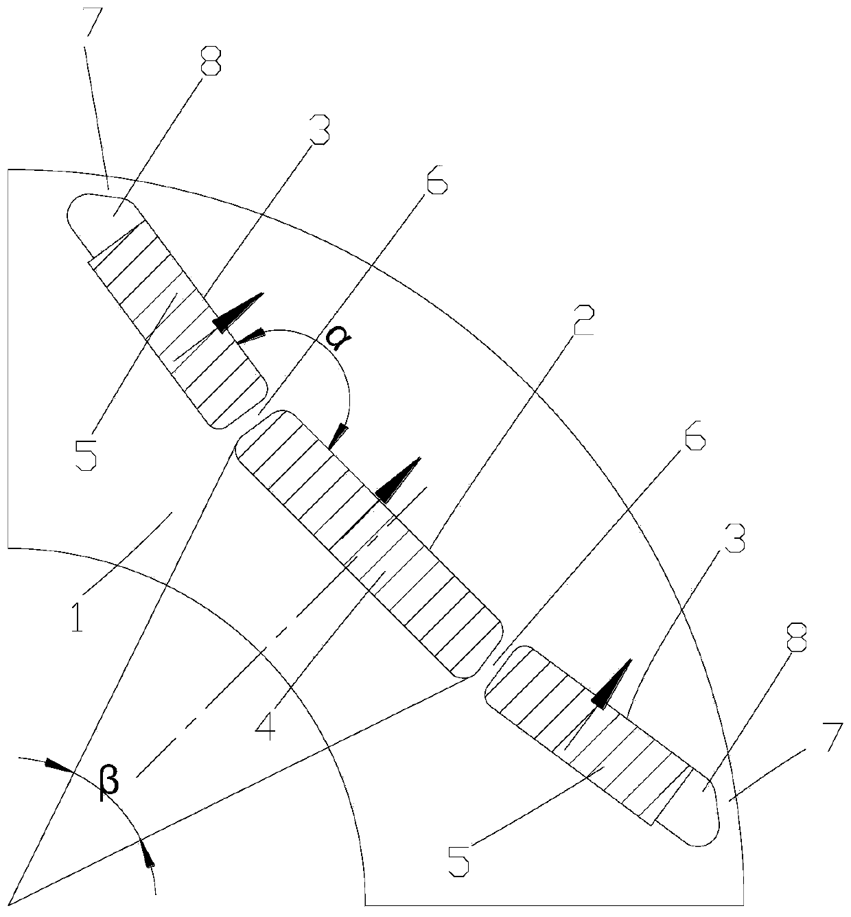
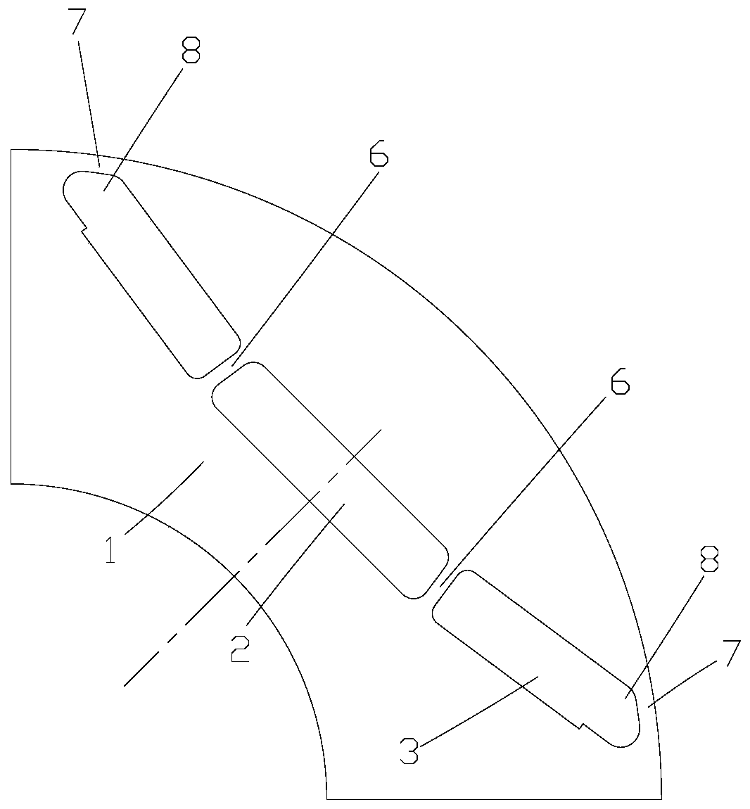
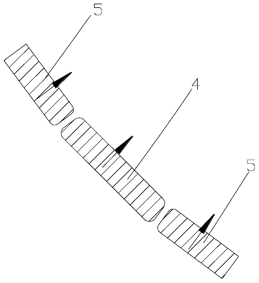
[0023] see in conjunction Figure 1 to Figure 4 As shown, according to the embodiment of the present application, the motor rotor includes a rotor core 1, and the rotor core 1 is provided with a first installation slot 2 perpendicular to the d-axis of the motor and two second installation slots located on both sides of the first installation slot 2. Mounting groove 3, the first mounting groove 2 is provided with the first permanent magnet 4, the second mounting groove 3 is provided with the second permanent magnet 5, the two second mounting grooves 3 are symmetrical about the motor d axis, the first mounting groove 2 An angle α is formed between the second mounting groove 3 and the side close to the outer circle of the rotor, where 155°≤α≤170°. Preferably, the first installation slot 2 is symmetrical about the d-axis of the motor.

[0024] In this application, by reasonably limiting the angle between the first installation groove 2 and the second installation groove 3, a suff...


PUM


Abstract

The invention provides a motor rotor and a motor. The motor rotor comprises a rotor core (1). The rotor core (1) is provided with a first installation groove (2) perpendicular to the d axis of the motor and two second installation grooves (3) located in the two sides of the first installation groove (2). A first permanent magnet (4) is arranged in the first installation groove (2). Second permanent magnets (5) are arranged in the second installation grooves (3). The two second installation grooves (3) are symmetrical about the d axis of the motor. An included angle alpha is formed between thefirst installation groove (2) and the second installation grooves (3), and alpha is larger than or equal to 155 degrees and smaller than or equal to 170 degrees. According to the motor rotor providedby the invention, the demagnetization resistance of the motor rotor can be effectively improved, and the output torque of the motor is ensured.

Description

technical field [0001] The present application relates to the field of motor technology, in particular to a motor rotor and a motor. Background technique [0002] High-speed permanent magnet synchronous motor has many advantages such as high power density, good dynamic response and simple structure, and has become one of the research hotspots in the field of international motors. Rotor strength is the core of high-speed motor design, and designing a high-strength rotor structure under the same material has become an important technology for high-speed motors. For the built-in high-speed motor rotor, the maximum stress generally occurs at the rib of the high-speed motor rotor, so increasing the strength of the rib has a significant effect on improving the strength of the rotor. [0003] In the prior art, in order to improve the structural strength of the motor rotor, magnetic steel sections are generally arranged, and reinforcing ribs are provided between two adjacent sectio...

Claims


Application Information

Patent Timeline
Patent Type & Authority Applications(China)
IPC IPC(8): H02K1/27H02K1/28
CPCH02K1/27H02K1/28
Inventor 张小波李广海张芳彭利明熊博文梁建东王珊珊张勐胡雄刘子彬龚从勇张前亮
Owner GREE ELECTRIC APPLIANCES INC
Why Eureka
Try Eureka