
Isolation sampling circuit

A sampling circuit and isolation sampling technology, applied in voltage/current isolation, measuring electrical variables, measuring devices, etc., can solve the problems of high power consumption and difficult temperature drift control, and achieve low power consumption, reasonable control, and less heat Effect

Pending Publication Date: 2020-05-05
湖南晟和电源科技有限公司
View PDF3 Cites 2 Cited by
  • Summary
  • Abstract
  • Description
  • Claims
  • Application Information

AI Technical Summary

Problems solved by technology

[0004] The main purpose of the present invention is to provide an isolated sampling circuit, which aims to solve the technical problems of high power consumption and difficult temperature drift control in the existing isolated sampling circuit

Method used


Image

  • Isolation sampling circuit
  • Isolation sampling circuit
  • Isolation sampling circuit

Examples


Embodiment Construction

[0056] It should be understood that the specific embodiments described here are only used to explain the present invention, not to limit the present invention.

[0057] The following will clearly and completely describe the technical solutions in the embodiments of the present invention with reference to the accompanying drawings in the embodiments of the present invention. Obviously, the described embodiments are only part of the embodiments of the present invention, not all of them. Based on the embodiments of the present invention, all other embodiments obtained by persons of ordinary skill in the art without creative efforts fall within the protection scope of the present invention.

[0058] It should be noted that all directional indications (such as up, down, left, right, front, back...) in the embodiments of the present invention are only used to explain the relationship between the components in a certain posture (as shown in the accompanying drawings). Relative positi...


PUM


Abstract

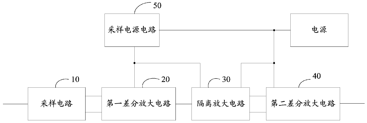
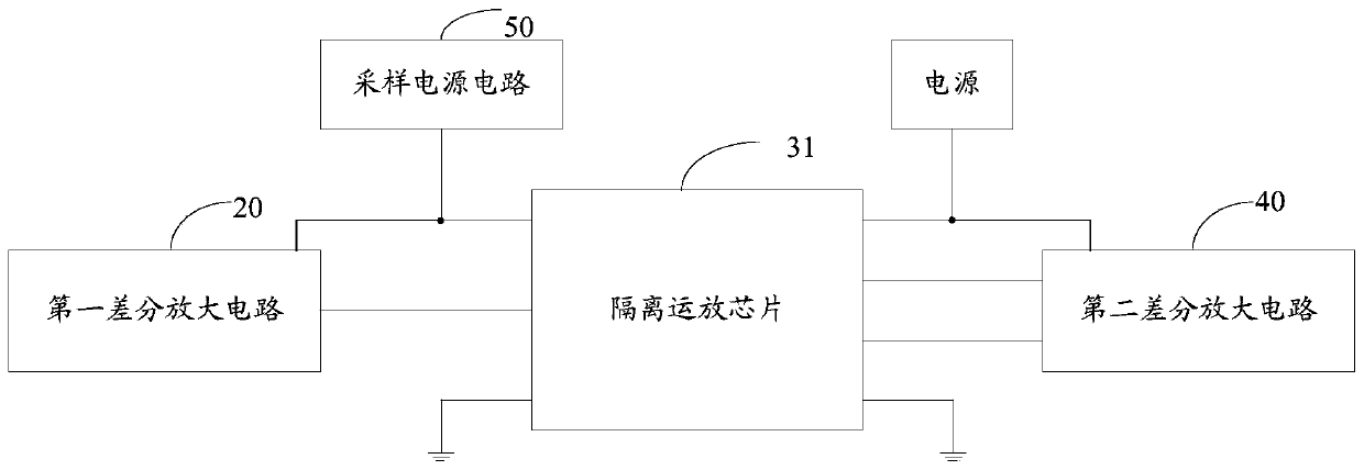
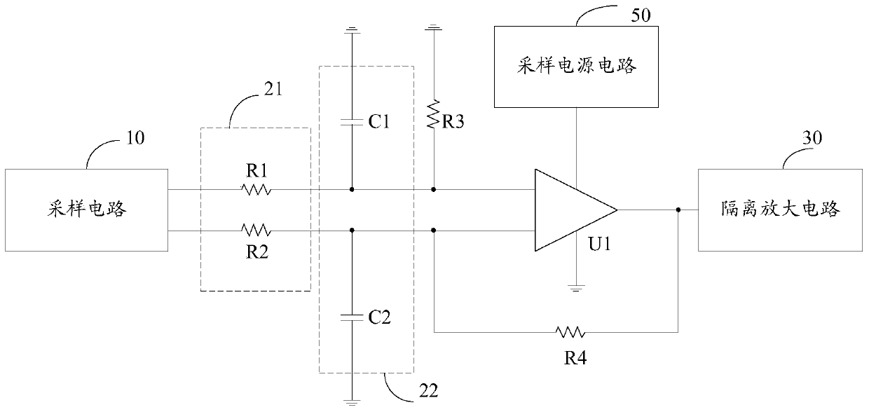
The invention discloses an isolation sampling circuit, wherein a first output end and a second output end of the sampling circuit are respectively connected with a first input end and a second input end of the first differential amplification circuit; the output end of the first differential amplification circuit is connected with the input end of the isolation amplification circuit, and the firstoutput end and the second output end of the isolation amplification circuit are connected with the first input end and the second input end of the second differential amplification circuit respectively; the output end of the sampling power supply circuit is connected with the power supply end of the first differential amplification circuit and the first power supply end of the isolation amplification circuit. The second power supply end of the isolation amplification circuit and the power supply end of the second differential amplification circuit are externally connected with a power supply.Because a Hall sensor and a shunt are not arranged in the isolation sampling circuit, the power consumption of the whole isolation sampling circuit is lower, and the generated heat is less, so that the temperature drift of the isolation sampling circuit is reasonably controlled.

Description

technical field [0001] The invention relates to the technical field of circuits, in particular to an isolated sampling circuit. Background technique [0002] In various electronic devices, an isolated sampling circuit is usually provided to perform isolated sampling on direct current or alternating current. [0003] In the existing circuits for isolated sampling of DC current, Hall sensors or shunts are usually used. Among the above components, the Hall sensor has a large volume, large power loss, difficult to control temperature drift, and high frequency Disadvantages such as limited bandwidth; the shunt also has the disadvantages of high power consumption and poor control of temperature drift. It is easy to understand that the isolated sampling circuit using Hall sensors or shunts also has the defects of high loss and difficult temperature drift control, so how to provide an isolated sampling circuit that can overcome the above defects is a technology to be solved in this...

Claims


Application Information

Patent Timeline
Patent Type & Authority Applications(China)
IPC IPC(8): H03F3/45G01R15/14
CPCH03F3/45G01R15/146
Inventor 吴思聪龙志进
Owner 湖南晟和电源科技有限公司
Learn More