Wide-angle compensation of uniaxial retarder stacks

A technology of retarder and stack, applied in the field of wide-angle compensation of single-axis retarder stack

Pending Publication Date: 2020-05-05
CTRL LABS CORP
View PDF10 Cites 0 Cited by
  • Summary
  • Abstract
  • Description
  • Claims
  • Application Information

AI Technical Summary

Problems solved by technology

But when polarizing optics must perform the same function regardless of the angle of incidence, R th often a problem

Method used


Image

  • Wide-angle compensation of uniaxial retarder stacks
  • Wide-angle compensation of uniaxial retarder stacks
  • Wide-angle compensation of uniaxial retarder stacks

Examples


example 1

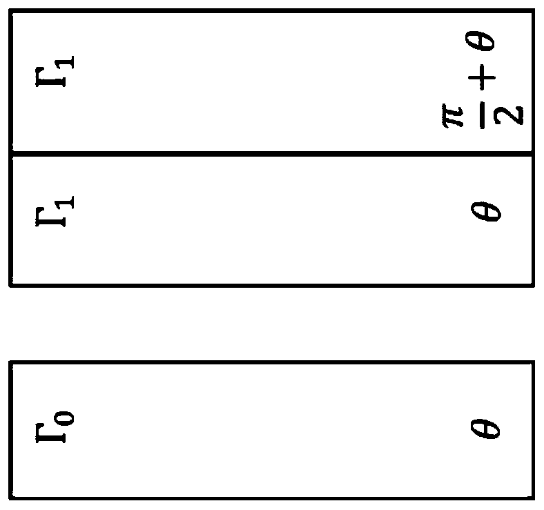
[0046] Example 1: 14-layer filter using inverse order reflection compensation around 45°

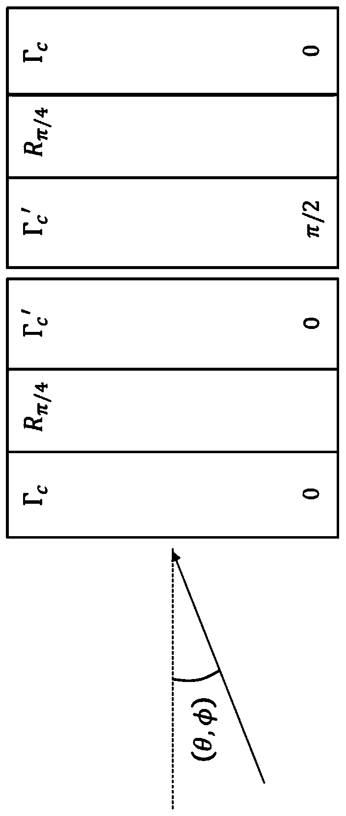
[0047] Use computer models to illustrate the relationship with Γ c and Γ c 'related R th C relative proportion. A 14-layer green-magenta filter with the design of Table 1, each layer having a 1.5-wave retardation at 530 nm, was used. Therefore, for each stack, R e C The value of is 5565nm at 530nm. Optimal performance at 25° incidence at 0 / 90° azimuth was obtained using cross-A plates, each with a retardation of 2100 nm. This should be the same as Γ c ' is a somewhat close match, indicating that Γ c About 3465nm. Each stack is then swapped end-to-end. Although the central delay should now be Γ c The delay of , but the rotation (which is the reciprocal) is basically preserved. After repeated optimization, the selected compensator value was 4200nm. Adding the two optimized compensation values ​​indicates that the total R e C is about 6300nm, which is fairly close to the abo...

example 2

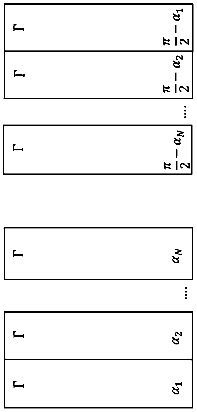
[0048] Example 2: 8-layer filter using reverse order reflection compensation around 45°

[0049] Figures 4 and 5 show the design of Table 1 with 8 layers at various angles of incidence (0-25°) between crossed ideal polarizers. Each layer has a 1.5-wave retardation at 540nm, giving a composite retardation of 3240nm for each stack. Figure 4a An uncompensated design along ±45° azimuth is shown, where the performance of both the passband and stopband is relatively stable. This indicates the stability of the non-perpendicularity of the rotational and composite optical axes, and the lack of Γ in this azimuth c 'Impact. Figure 4b An uncompensated design for 0 / 90° azimuth is shown. Note that the composite optical axis keeps the wavelength stable, so the unconverted band does not vary much, so there is little leakage in the blue / red part of the spectrum. As the green performance decreases with angle of incidence, it takes the form of a loss in peak transmittance. There is no app...


PUM


Abstract

A compound retarder that creates independent control of Re and Rth. This can be done by forming a three-layer compound retarder, including a pair of matched -A-plates, combined with single +A-plate. The +A-plate is typically an MD-stretched film, with retardation that is specific to the in-plane requirements (Re) of the application. The pair of -A-plates have their optic axes crossed, such that Re=0, with an optic axis aligned parallel to the +A-plate. A single retardation value for the -A-plate can produce improved field-of-view performance over a broad range of Re values, making it a very practical means of universal compensation. While Rth is typically associated with a single retarder, retarder stacks with a diverse range of optic-axis orientations can be considered to have a compound(or composite) Rth value (Rcth). The three-layer compound retarder has the practical benefit of enabling field-of-view compensation across a broad range of normal-incidence polarization transformations.

Description

[0001] Cross References to Related Applications [0002] This application claims priority to US Provisional Application No. 62 / 533,547, filed July 17, 2017, the entire contents of which are hereby incorporated by reference. Background technique [0003] Optical components that switch between orthogonal states of polarization (SOP) are often required. Almost all polarizers used in products today eliminate or reflect a linear SOP, thus making a linear reference a reality for most polarization conversion scenarios. This conversion is typically accomplished using one or more linear delays. There is also often a need to maintain conversion over an extended range of wavelengths and angles of incidence. In some cases it may further be desirable that there be a separate wavelength range over which the input SOP is preserved (not converted). This additional constraint applies mainly to systems that distinguish between wavelength bands, typically for filtering, splitting / combining, o...

Claims


Application Information

Patent Timeline
IPC IPC(8): G02B27/64
CPCG02B5/3083G02F2413/03G02F2413/08G02F2413/14G02F1/13363G02F1/133634
Inventor 加里.D.夏普
Owner CTRL LABS CORP
Why Eureka
Try Eureka