
Near-infrared cut filter and imaging device

a filter and near-infrared technology, applied in the field of near-infrared cut filters and imaging devices, can solve the problems of different color reproducibility depending on the incident angle, unsolved problems, and inability to obtain color reproducibility particularly of redness with high accuracy, and achieve the effect of small incident angle dependence and excellent color reproducibility

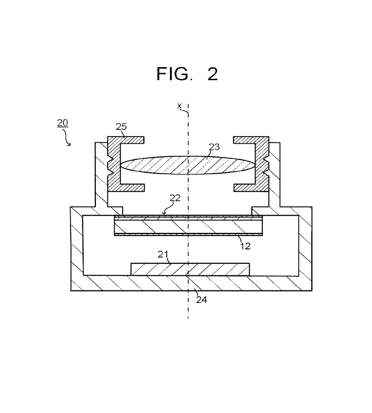
Active Publication Date: 2019-07-30
ASAHI GLASS CO LTD
View PDF70 Cites 0 Cited by
  • Summary
  • Abstract
  • Description
  • Claims
  • Application Information

AI Technical Summary

Benefits of technology

The patent aims to provide a near-infrared cut filter that has a spectral characteristic close to the relative visibility curve, especially on the long wavelength side, and has small incident angle dependence. This filter has excellent oblique-incidence properties, which can improve color reproduction in imaging devices. Essentially, the invention provides a solution for improving the color accuracy of near-infrared filters.

Problems solved by technology

Thus, there is a problem that it has incident angle dependence in its spectral characteristic, and that color reproducibility is different depending on the incident angle.
However, the incident angle dependence is recognized also in this filter, and the problem of different color reproducibility depending on the incident angle remains unsolved.
In this filter, for example, the wavelength at which transmittance becomes 50% is in the vicinity of 650 nm, and the transmittance on a long wavelength side is high with reference to a relative visibility curve, having a problem that color reproducibility particularly of redness cannot be obtained with high accuracy.
However, the above-described incident angle dependence of the spectral characteristic of this filter is large, and there is still a problem that color reproducibility differs depending on the incident angle.
As described above, among the conventional near-infrared cut filters, there are few that have the spectral characteristic close to the relative visibility curve particularly on the long wavelength side, and even those having such a spectral characteristic close to the relative visibility curve, there is a problem that there is incident angle dependence in their spectral characteristics.
Thus, good color reproducibility cannot be obtained.

Method used


Image

  • Near-infrared cut filter and imaging device
  • Near-infrared cut filter and imaging device
  • Near-infrared cut filter and imaging device

Examples


example 1

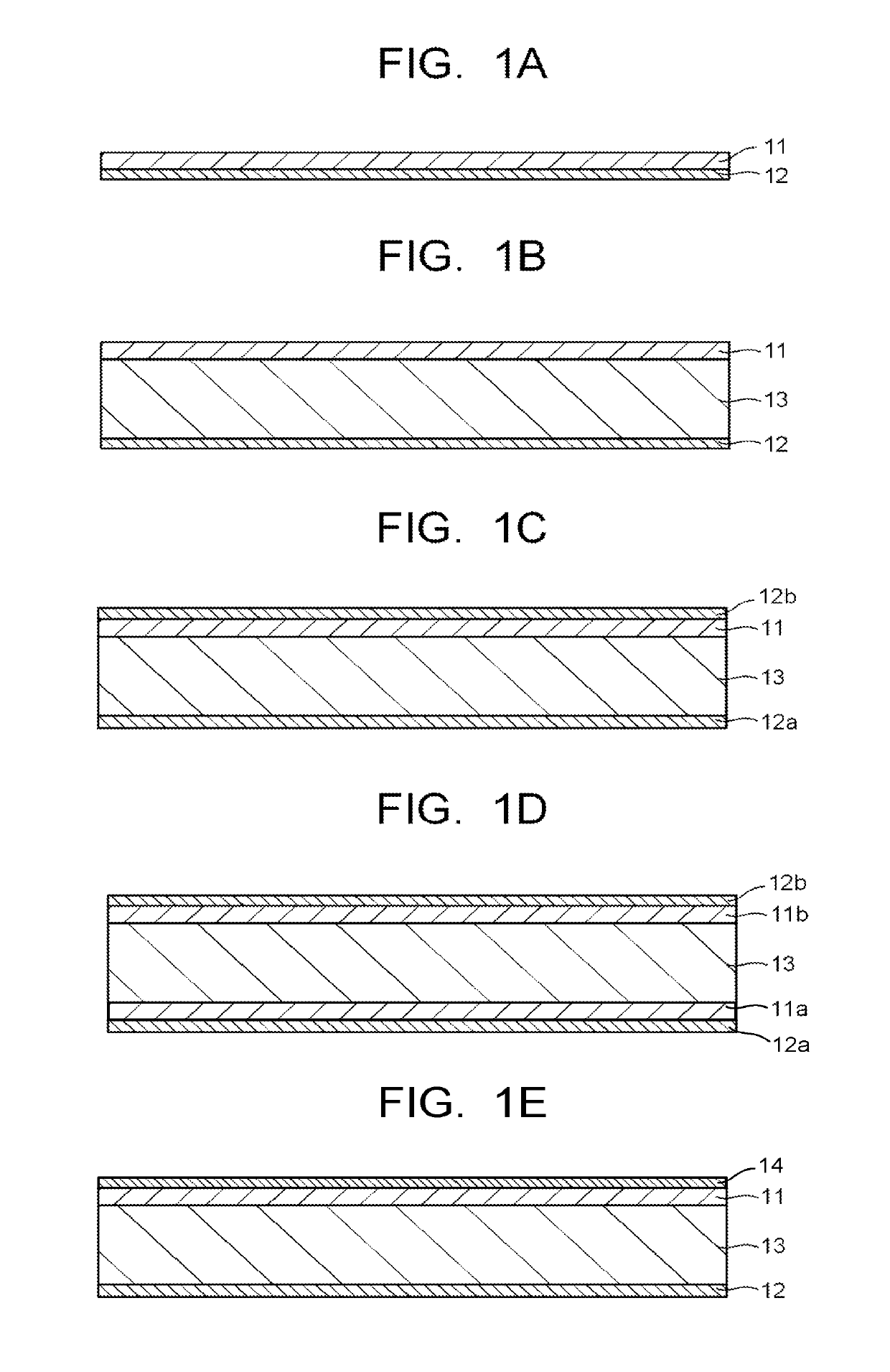
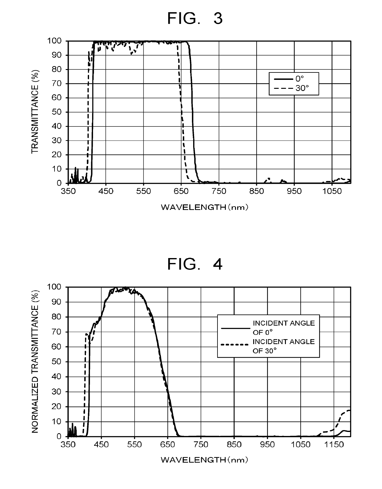
[0228]On a glass (none-alkali glass; product name: AN100, manufactured by Asahi Glass Co., Ltd.) substrate having a thickness of 0.3 mm, a TiO2 film as a high-refractive index film and an SiO2 film as a low-refractive index film were stacked alternately by a vapor deposition method, thereby forming a reflection layer constituted of an dielectric multilayer film of 52 layers. The structure of the reflection layer was obtained by performing a simulation with the number of stacks of the dielectric multilayer film, a film thickness of the TiO2 film and a film thickness of the SiO2 film being parameters, so that transmittance with a wavelength of 350 to 400 nm is 10% or less, transmittance with a wavelength of 420 to 695 nm is 90% or more, and transmittance with a wavelength of 750 to 1100 nm is 10% or less in the spectral transmittance curve at an incident angle of 0°. FIG. 3 illustrates a spectral transmittance curve (incident angles of 0° and 30°) of a reflection layer produced based ...

examples 2 to 8

[0232]NIR filters were produced similarly to Example 1 while changing the type and / or addition amount of an NIR absorbing dye to be added to the coating liquid for forming the absorption layer as described in Table 3, except that in Example 5 and Example 6 an UV absorbing dye is further added by a ratio described in Table 3 in addition to the NIR absorbing dye.

example 9

[0233]An NIR filter was produced similarly to Example 1 except that the glass substrate was a fluorophosphate glass (product name: NF-50T, 0.25 mm thickness, manufactured by Asahi Glass Co., Ltd.) substrate, and the types and / or addition amounts of a transparent resin, an NIR absorbing dye and a UV absorbing dye used in the coating liquid for forming the absorption layer were set as described in Table 3.

[0234](Spectral Characteristic of the Absorption Layer)

[0235]Separately from the production of the above-described NIR filters, the coating liquid for forming an absorption layer prepared in each of the above examples was applied by a spin coating method on a glass substrate, and then heated under an atmospheric pressure for five minutes at 90° C. and then one hour at 150° C., thereby forming an absorption layer with a thickness of 1 μm.

[0236]The spectral transmittance curve of each absorption layer formed was measured with the atmospheric air being the background by using an ultravi...


PUM

PropertyMeasurementUnit
incident angleaaaaaaaaaa
transmittanceaaaaaaaaaa
wavelength rangeaaaaaaaaaa

Abstract

A near-infrared cut filter has an absorption layer and a reflection layer and satisfies following requirements:average transmittance (R) of 620-750 nm is ≤20%, average transmittance (G) of 495-570 nm is ≥90%, and a ratio (R) / (G) is ≤0.20;|T0(600-725)−T30(600-725)| is ≤3%·nm where T0(600-725) is a transmittance integral value of 600-725 nm in a spectral transmittance curve (0°), and T30(600-725) is a transmittance integral value of 600-725 nm in a spectral transmittance curve (30°);wavelengths λIRT(80), λIRT(50), and λIRT(20) where transmittance becomes 80%, 50%, and 20% respectively in 550-750 nm in the spectral transmittance curve (0°) normalized by maximum transmittance in 450-650 nm satisfy following formulae: 0≤λIRT(80)−λT(80)≤30 nm, 0≤λIRT(50)−λT(50)≤35 nm, and 0≤λIRT(20)−λT(20)≤37 nm where λT(80), λT(50), and λT(20) are wavelengths on a long wavelength side where relative visibility of 0.8, 0.5 and 0.2 is exhibited in a relative visibility curve.

Description

CROSS-REFERENCE TO RELATED APPLICATIONS[0001]The present application is a continuation of prior International Application No. PCT / JP2016 / 051021 filed on Jan. 14, 2016 which is based upon and claims the benefit of priority from Japanese Patent Applications Nos. 2015-005383 filed on Jan. 14, 2015, and 2015-163264 fled on Aug. 20, 2015; the entire contents of all of which are incorporated herein by reference.FIELD[0002]Embodiments described herein relate generally to a near-infrared cut filter and an imaging device.BACKGROUND ART[0003]In an imaging device using a solid-state image sensing device of a digital still camera or the like, a near-infrared cut filter transmitting visible light but blocking infrared light is typically disposed in an optical path to the solid-state image sensing device, so as to make the sensitivity of the solid-state image sensing device close to the visibility of human.[0004]As such a near-infrared cut filter, a filter is known in which an absorption layer co...

Claims


Application Information

Patent Timeline
Patent Type & Authority Patents(United States)
IPC IPC(8): C07D209/08G02B5/22G02B5/26C07D207/20G02B5/20
CPCG02B5/208C07D207/20G02B5/26G02B5/22G02B5/223C07D209/08G02B5/282
Inventor HASEGAWA, MAKOTOSUGIYAMA, TAKASHI
Owner ASAHI GLASS CO LTD
Learn More