Atomizer having zigzag airflow passage

An airflow channel and atomizer technology, applied in the field of electronic cigarettes, can solve the problems of affecting the smoking experience of the smoker, the conversion efficiency of the heating wire is not high, and the mouth of the smoker is burned, so as to improve the amount of atomization and suction Experience, avoid local burning, and improve the effect of utilization

Pending Publication Date: 2020-05-08
CHINA TOBACCO YUNNAN IND
View PDF0 Cites 1 Cited by
  • Summary
  • Abstract
  • Description
  • Claims
  • Application Information

AI Technical Summary

Problems solved by technology

[0002] When the current electronic cigarette is used, the oil-conducting cotton absorbs the smoke oil in the oil inlet hole to the oil-conducting cotton for atomization by the heating wire. After the wire is energized, heat is generated, and then the smoke oil on the oil-conducting cotton is atomized. Since the heating wire is one by one, the place where the heating wire contacts the oil-conducting cotton first generates heat, and the part that does not contact the oil-conducting cotton The temperature in the place is lower, or heat needs to be conducted to this place to generate heat, so the temperature difference is too large and the oil-conducting cotton will be partially burnt, that is, the position where the heating wire contacts the oil-conducting cotton will burn, which will affect the suction. vaping experience
In addition, the heating wire generates heat and converts electric energy into heat energy. The conversion efficiency of this resistive heating heating wire is not high in energy conversion and takes a long time, which affects the pumping experience of the smoker.
In addition, the atomization temperature of some e-cigarettes in the prior art is relatively high. If it cannot be sucked by the smoker after cooling to a certain temperature, it is easy to burn the mouth of the smoker.

Method used


Image

  • Atomizer having zigzag airflow passage
  • Atomizer having zigzag airflow passage
  • Atomizer having zigzag airflow passage

Examples


Embodiment Construction

[0047] The following will clearly and completely describe the technical solutions in the embodiments of the present invention with reference to the accompanying drawings in the embodiments of the present invention. Obviously, the described embodiments are only some, not all, embodiments of the present invention. Based on the embodiments of the present invention, all other embodiments obtained by persons of ordinary skill in the art without making creative efforts belong to the protection scope of the present invention.

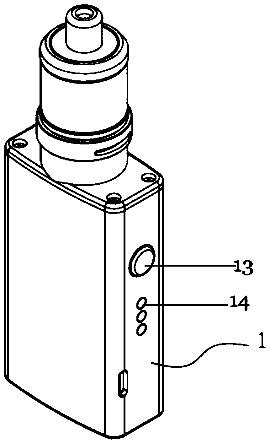
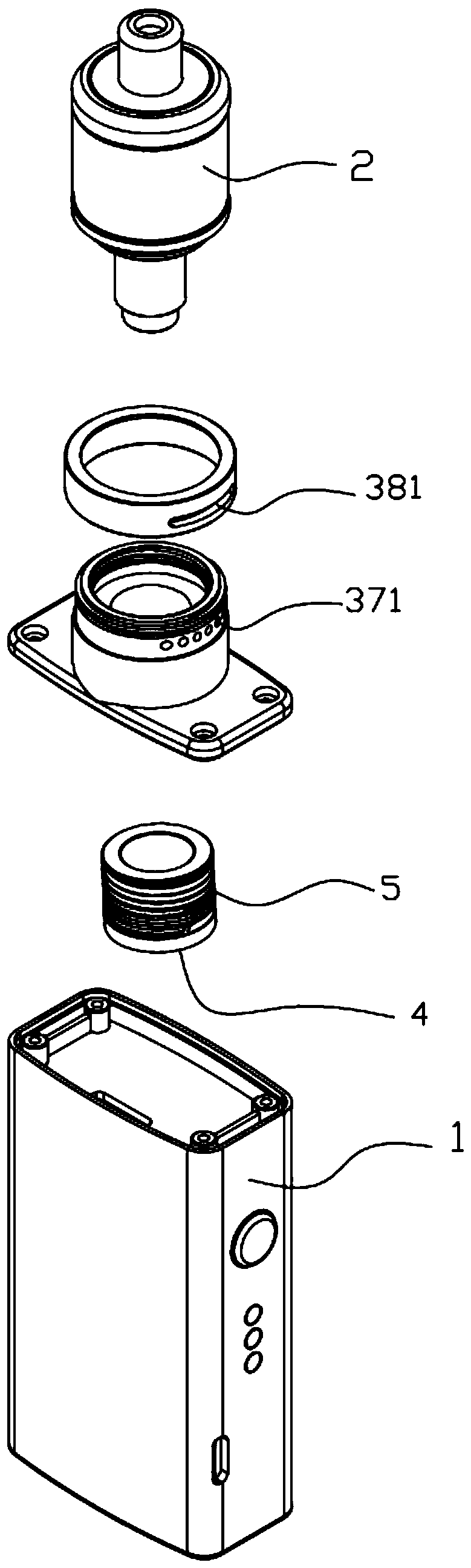
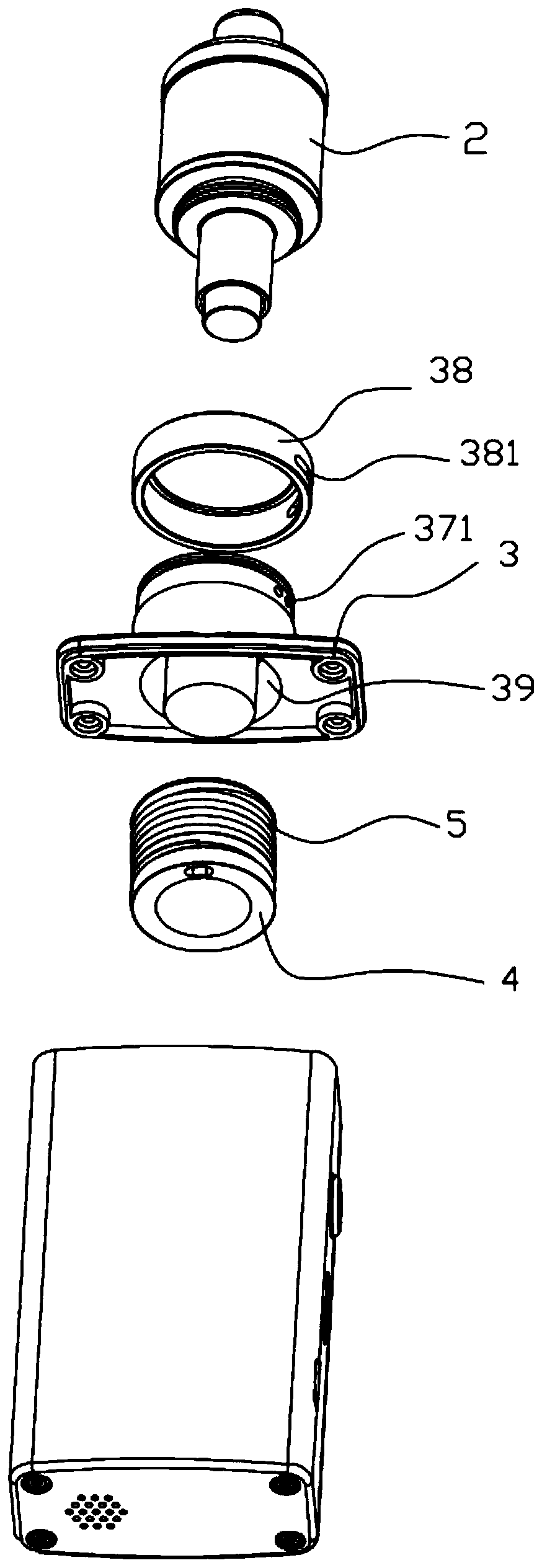
[0048] Such as Figure 1-Figure 10 , the embodiment of the present invention provides an atomizer and a smoking appliance based on electromagnetic induction heating, and these components are introduced separately below.

[0049] An atomizer with a tortuous airflow channel, which includes: an atomization chamber 2, including an atomization core 26, and the atomization core 26 includes a ferromagnetic heating tube 267 and an oil-conducting cotton 266 wrapped by ...


PUM


Abstract

The invention discloses an atomizer with a zigzag airflow channel. The atomizer comprises an atomizing chamber (2), an induction coil (5) and an atomizing cup (31). The atomizing chamber (2) comprisesan atomizing core (26), the atomizing core (26) comprises a ferromagnetic heating tube (267) and oil guide cotton (266) wrapping the ferromagnetic heating tube (267), and the ferromagnetic heating tube (267) is provided with a plurality of holes. The atomizing cup (31) has a non-ferromagnetic cup wall (32). The atomizing chamber (2) is located in the atomizing cup (31), and the induction coil (5)sleeves the outer side of the non-ferromagnetic cup wall (32). The atomizing core (26) is isolated from the induction coil (5) through the non-ferromagnetic cup wall (32). Due to the design that theinduction coil is completely isolated from the atomizing chamber, tobacco tar in the atomizing chamber can be effectively prevented from contaminating and damaging the induction coil, and the servicelife of the induction coil is prolonged. According to the atomizer, a bent airflow channel is adopted, the temperature of smoke entering the oral cavity can be reduced, and the oral cavity is prevented from being scalded.

Description

technical field [0001] The invention belongs to the technical field of electronic cigarettes, and in particular relates to an atomizer with a tortuous airflow channel. Background technique [0002] When the current electronic cigarette is used, the oil-conducting cotton absorbs the smoke oil in the oil inlet hole to the oil-conducting cotton for atomization by the heating wire. After the wire is energized, heat is generated, and then the smoke oil on the oil-conducting cotton is atomized. Since the heating wire is one by one, the place where the heating wire contacts the oil-conducting cotton first generates heat, and the part that does not contact the oil-conducting cotton The temperature in the place is lower, or heat needs to be conducted to this place to generate heat, so the temperature difference is too large and the oil-conducting cotton will be partially burnt, that is, the position where the heating wire contacts the oil-conducting cotton will burn, which will affec...

Claims


Application Information

Patent Timeline
Patent Type & Authority Applications(China)
IPC IPC(8): A24F40/465A24F40/42
Inventor 李廷华尤俊衡朱东来陈永宽杨强韩熠李寿波张霞巩效伟赵伟
Owner CHINA TOBACCO YUNNAN IND
Why Eureka
Try Eureka