Device for cleaning shoes

A technology for shoes and bevel gears, which is applied to household cleaning devices, cleaning and application of boots and shoes, etc., can solve problems such as inability to clean shoes, and achieve the effects of simple structure, convenient use and convenient cleaning.

Inactive Publication Date: 2020-05-08
ZHEJIANG DA BO WEN SHOES CO LTD
20 Cites 0 Cited by

AI-Extracted Technical Summary

Problems solved by technology

However, it is always impossible to clean up the stained sho...

Abstract

The invention discloses a device for cleaning shoes. The device comprises a device body. A sliding groove is formed in the device body. A first sliding block is mounted in the sliding groove in a sliding manner, and the first sliding block is elastically connected with the sliding groove. A fixing block is fixedly mounted above the first sliding block, and a sensing device is fixedly mounted in the fixing block. The first sliding block is connected with a first connecting line. A fixing plate is arranged on the right side of the sliding groove. A winding groove is formed in the right side of the fixing plate. A reel is rotationally mounted in the winding groove, and the reel is connected with the first connecting line. A driving device is arranged on the rear side of the reel. The device is simple in structure and convenient to use. The device is provided with a cleaning mechanism, shoes can be conveniently cleaned, the device can automatically clean the shoes, and greater convenienceis brought. The device is provided with the sensing device, so that the shoes placed on the device can be effectively sensed.

Application Domain

Footwear cleaners

Technology Topic

Structural engineeringMechanical engineering

Image

  • Device for cleaning shoes
  • Device for cleaning shoes
  • Device for cleaning shoes

Examples

  • Experimental program(1)

Example Embodiment

[0014] All the features disclosed in this specification, or all disclosed methods or steps in the process, except for mutually exclusive features and/or steps, can be combined in any manner.
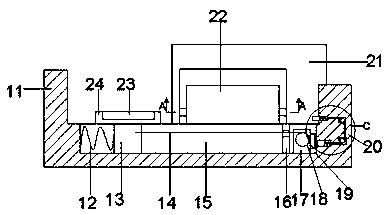
[0015] Combine below Figure 1-4 The present invention will be described in detail. For the convenience of description, the following directions are specified as follows: figure 1 The vertical, horizontal, front and rear directions of the projection relationship are the same.
[0016] A device for cleaning shoes of the device of the present invention includes a device body 11, a sliding groove 15 is provided in the device body 11, and a first sliding block 13 is slidably mounted in the sliding groove 15 and the first sliding The block 13 and the sliding groove 15 are elastically connected by 12, a fixed block 24 is fixedly installed above the first sliding block 13, a sensing device 23 is fixedly installed in the fixed block 24, and the first sliding block 13 is connected There is a first wire 14, the sliding groove 15 is provided with a fixing plate 16 on the right side, and the fixing plate 16 is provided with a winding groove 19 on the right side. A winding wheel 18 is rotatably installed in the winding groove 19, so A first wire 14 is connected to the winding wheel 18, a driving device 17 is provided on the rear side of the winding wheel 18, a closing button 68 is provided at the right end of the driving device 17, and the right side of the winding groove 19 is provided with The trigger device 20 is provided with a cleaning frame 21 on the rear side of the device body 11, and the cleaning frame 21 is provided with a cleaning mechanism 22.
[0017] Advantageously, the cleaning mechanism 22 includes a first bevel gear groove 32 arranged in the cleaning frame 21, a first rotation shaft 35 is rotatably installed between the first bevel gear grooves 32, and the first rotation shaft A cleaning brush 34 is fixedly installed on the 35. The left and right ends of the first rotating shaft 35 extend into the first bevel gear groove 32 and are fixedly installed with a first bevel gear 36. The first bevel gear groove 32 is provided with a first bevel gear. Two bevel gear grooves 42, a threaded sleeve 38 and a threaded rod 39 are rotatably installed between the second bevel gear groove 42 and the first bevel gear groove 32, and the front end of the threaded sleeve 38 extends into the first bevel gear groove 32 and A second bevel gear 37 is rotatably installed, the second bevel gear 37 is meshed with the first bevel gear 36, a first spring groove 30 is provided between the threaded sleeve 38 and the threaded rod 39, and the threaded sleeve 38 is connected to The threaded rods 39 are elastically connected by the first spring 31. The rear end of the threaded rod 39 extends into the second bevel gear groove 42 and is fixedly installed with a third bevel gear 40. The second bevel gear grooves 42 are arranged between There is a third bevel gear groove 33, a second rotation shaft 29 is rotatably mounted between the third bevel gear groove 33 and the second bevel gear groove 42, and the outer end of the second rotation shaft 29 extends into the second bevel gear The groove 42 is fixedly installed with a fourth bevel gear 41. The fourth bevel gear 41 is meshed and connected with the third bevel gear 40. The inner end of the second rotating shaft 29 extends into the third bevel gear groove 33 and is fixedly installed with For the fifth bevel gear 28, a gear groove 44 is provided on the rear side of the third bevel gear groove 33, a third rotating shaft 26 is rotatably mounted between the gear groove 44 and the third bevel gear groove 33, and the third rotation The front end of the shaft 26 extends into the third bevel gear groove 33 and is fixedly installed with a sixth bevel gear 27. The sixth bevel gear 27 is in meshing connection with the fifth bevel gear 28, and the rear end of the third rotating shaft 26 extends into The gear groove 44 is fixedly installed with the first gear 25.
[0018] Advantageously, a fourth bevel gear groove 47 is provided behind the gear groove 44, a fourth rotation shaft 45 is rotatably mounted between the fourth bevel gear groove 47 and the gear groove 44, and the front end of the fourth rotation shaft 45 extends Into the gear groove 44 and fixedly installed with a second gear 43, the second gear 43 meshingly connected with the first gear 25, the rear end of the fourth rotating shaft 45 extends into the fourth bevel gear groove 47 and fixedly installed A seventh bevel gear 46, a fifth bevel gear groove 50 located on the rear side of the winding groove 19 is provided under the fourth bevel gear groove 47, and the fifth bevel gear groove 50 and the fourth bevel gear groove 47 rotate between A fifth rotating shaft 48 is installed. The upper end of the fifth rotating shaft 48 extends into the fourth bevel gear groove 47 and is fixedly installed with an eighth bevel gear 70. The eighth bevel gear 70 is in meshing connection with the seventh bevel gear 46 , The lower end of the fifth rotating shaft 48 extends into the fifth bevel gear groove 50 and is fixedly installed with a ninth bevel gear 49, and a sixth rotating shaft is rotatably installed between the winding groove 19 and the fifth bevel gear groove 50 53. The rear end of the sixth rotating shaft 53 extends into the fifth bevel gear groove 50 and is fixedly installed with a tenth bevel gear 51. The tenth bevel gear 51 is in meshing connection with the ninth bevel gear 49. The front end of the rotating shaft 53 extends into the winding groove 19 and is in power connection with the driving device 17.
[0019] Advantageously, the trigger device 20 includes a second spring groove 58 arranged on the right side of the winding groove 19, and a second slider 57 is slidably mounted in the second spring groove 58. The second slider 57 It is elastically connected with the second spring groove 58 through 59, the second sliding block 57 is connected with a second wire 63, the right side of the second spring groove 58 is provided with a first wire groove 60, the first A first wire reel groove 61 is provided on the right side of the wire groove 60, a first wire reel 62 is rotatably installed in the first wire reel groove 61, and a second wire groove 64 is provided above the first wire reel groove 61. A second wire reel groove 66 is provided above the second wire groove 64, a second wire reel 65 is rotatably installed in the second wire reel groove 66, a third wire groove 67 is provided on the left side of the second wire reel groove 66, and the third wire groove 67 is provided with a third spring groove 54 on the left side, a third sliding block 56 is slidably mounted in the third spring groove 54, and the third sliding block 56 and the third spring groove 54 are elastically connected by 55, the A second wire groove 64 is connected to the third sliding block 56, and the second wire groove 64 is fixedly connected to the second sliding block 57 through the second wire wheel 65 and the first wire wheel 62 from the third sliding block 56 in turn.
[0020] When starting to work, put the shoes on the fixed block 24, the induction device 23 generates induction and activates the driving device 17, and the driving device 17 drives the winding wheel 18 to wind, so that the winding wheel 18 passes through the first connecting The wire 14 pulls the first sliding block 13 to move to the right, and the first sliding block 13 drives the fixed block 24 to move to the right. When the driving device 17 is activated, the driving device 17 drives the tenth cone through the sixth rotating shaft 53 The gear 51 rotates, so that the tenth bevel gear 51 meshes with the ninth bevel gear 49 for transmission, and the ninth bevel gear 49 drives the eighth bevel gear 70 to rotate through the fifth rotation shaft 48, so that the eighth bevel gear 70 meshes with the seventh bevel gear 46 for transmission, and the seventh bevel gear 46 drives the second gear 43 to rotate through the fourth rotation shaft 45, so that the second gear 43 meshes with the first gear 25 for transmission, and the A gear 25 drives the sixth bevel gear 27 to rotate through the third rotating shaft 26, so that the sixth bevel gear 27 meshes with the fifth bevel gear 28, and the fifth bevel gear 28 drives the second bevel gear through the second rotating shaft 29. The four bevel gear 41 rotates, so that the fourth bevel gear 41 meshes with the third bevel gear 40 for transmission, and the third bevel gear 40 drives the second bevel gear 37 to rotate through the threaded rod 39 and the threaded sleeve 38, so that the The second bevel gear 37 meshes with the first bevel gear 36 for transmission, and the first bevel gear 36 drives the cleaning brush 34 to rotate through the first rotating shaft 35. When the fixed block 24 pushes the third sliding block 56 to move to the right, the 59 performs elastic recovery, so that the 59 pushes the second sliding block 57 to move to the left to activate the closing button 68 and close the driving device 17.
[0021] The above are only specific embodiments of the invention, but the scope of protection of the invention is not limited to this. Any changes or substitutions that are not thought of through creative work should be covered by the scope of protection of the invention. Therefore, the protection scope of the invention should be subject to the protection scope defined by the claims.

PUM

no PUM

Description & Claims & Application Information

We can also present the details of the Description, Claims and Application information to help users get a comprehensive understanding of the technical details of the patent, such as background art, summary of invention, brief description of drawings, description of embodiments, and other original content. On the other hand, users can also determine the specific scope of protection of the technology through the list of claims; as well as understand the changes in the life cycle of the technology with the presentation of the patent timeline. Login to view more.

Similar technology patents

Photoelectric sensor for position of sun

InactiveCN101650173AEffective tracking range expandedSimple structure
Owner:WUHAN UNIV OF TECH

Magnetic cooling apparatus and control method thereof

ActiveUS20130180263A1simple structure
Owner:SAMSUNG ELECTRONICS CO LTD

Dual-Drivetrain of Power-Assist Vehicle

InactiveUS20100181130A1enhance uphill momentumsimple structure
Owner:CHOU WEN CHENG

Classification and recommendation of technical efficacy words

  • Simple structure
  • easy to use

Laser assisted total joint arthroplasty

InactiveUS20090234360A1easy to use
Owner:ALEXANDER VLADIMIR

Enclosure for a portable hemodialysis system

ActiveUS20090114582A1easy to use
Owner:DEKA PROD LLP
Why Eureka
Try Eureka