High-efficiency blowing type transformer radiator cleaning device and cleaning method

A cleaning device and transformer technology, applied in the field of transformers, can solve the problems of transformer safety hazards, time-consuming and labor-intensive, unable to separate by itself, and achieve the effect of improving work efficiency and efficient cleaning work

Inactive Publication Date: 2020-05-08
河南省森电智能装备有限公司
View PDF10 Cites 0 Cited by
  • Summary
  • Abstract
  • Description
  • Claims
  • Application Information

AI Technical Summary

Problems solved by technology

[0002] In the power system, the transformer radiator of the substation is placed outdoors. Dust, flakes and other pollutants in the environment are easily adsorbed on the surface of the radiator and cannot be separated by themselves. If these substances adsorbed on the surface of the transformer radiator are not removed in time Cleaning more and more will reduce the cooling effect of the transformer radiator, increase the temperature of the transformer, affect the normal working state of the transformer, and cause potential safety hazards in the transformer
[0003] The existing method is to carry out regular cleaning and water flushing, but the radiator fins are large and the spacing is small. Traditionally, only the surface is carried out, and the interior of the radiator fins cannot be cleaned, and the cleaning effect has not been achieved. At the same time, due to the high installation of the transformer radiator , need to ascend to work, there are risks in the operation, and the operation is time-consuming and labor-intensive. So far, there is no better solution

Method used

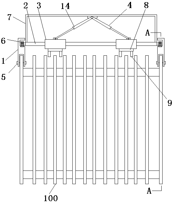
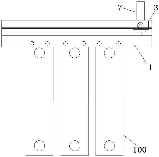
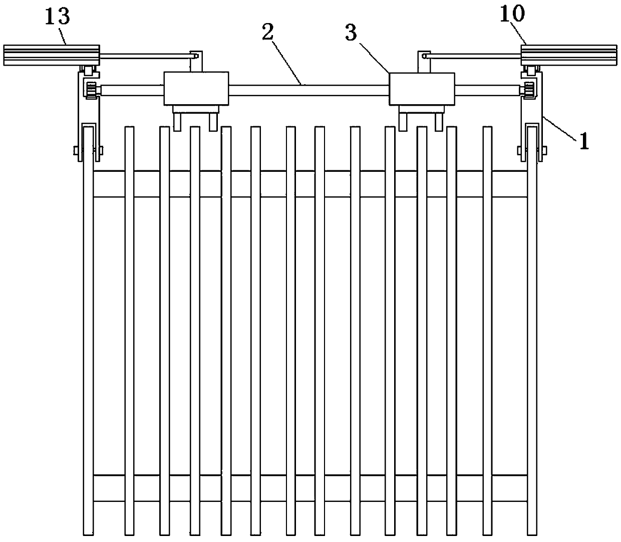

Image

  • High-efficiency blowing type transformer radiator cleaning device and cleaning method
  • High-efficiency blowing type transformer radiator cleaning device and cleaning method
  • High-efficiency blowing type transformer radiator cleaning device and cleaning method

Examples


Embodiment Construction

[0036] In order to make the objectives, technical solutions and advantages of the present invention clearer, the technical solutions in the embodiments of the present invention will be described in more detail below in conjunction with the drawings in the embodiments of the present invention. In the drawings, the same or similar reference numerals denote the same or similar elements or elements having the same or similar functions throughout. The described embodiments are some, but not all, embodiments of the invention. The embodiments described below by referring to the figures are exemplary and are intended to explain the present invention and should not be construed as limiting the present invention. Based on the embodiments of the present invention, all other embodiments obtained by persons of ordinary skill in the art without making creative efforts belong to the protection scope of the present invention. Embodiments of the present invention will be described in detail b...


PUM


Abstract

The invention discloses a high-efficiency blowing type transformer radiator cleaning device. The cleaning device is installed on a transformer radiator, and the cleaning device comprises a longitudinal walking mechanism, a transverse walking mechanism and high-pressure air blowing devices. The longitudinal walking mechanism comprises two symmetrical fixed guide rails and a moving guide rail, wherein one fixed guide rail is mounted on the top of each of two heat dissipation sheets at the outermost side of a high-voltage transformer; the moving guide rail spans between the two fixed guide rails,and the operation of the moving guide rail is realized through a longitudinal walking component. The transverse walking mechanism comprises two box bodies, wherein the two box bodies are slidably connected to the moving guide rail; the left side box body runs in the left half part of the moving guide rail through a left side transverse walking component, and the right side box body runs in the right half part of the moving guide rail through a right side transverse walking component. The high-pressure air blowing devices are installed on the box bodies and used for blowing air between the twoadjacent dissipation sheets. According to the invention, full-automatic cleaning is achieved, manual adjustment is not needed, and the working efficiency is improved.

Description

technical field [0001] The invention relates to the field of transformers, in particular to a high-efficiency blowing type transformer radiator cleaning device. Background technique [0002] In the power system, the transformer radiator of the substation is placed outdoors. Dust, flakes and other pollutants in the environment are easily adsorbed on the surface of the radiator and cannot be separated by themselves. If these substances adsorbed on the surface of the transformer radiator are not removed in time Cleaning more and more will reduce the cooling effect of the transformer radiator, increase the temperature of the transformer, affect the normal working state of the transformer, and cause potential safety hazards in the transformer. [0003] The existing method is to carry out regular cleaning and water flushing, but the radiator fins are large and the spacing is small. Traditionally, only the surface is carried out, and the interior of the radiator fins cannot be clea...

Claims


Application Information

Patent Timeline
Patent Type & Authority Applications(China)
IPC IPC(8): B08B5/02H01F27/22H01F27/00
CPCB08B5/02H01F27/00H01F27/22
Inventor 李勇董琦邸俊俊薛云
Owner 河南省森电智能装备有限公司
Why Eureka
Try Eureka