Deformable wing

A wing and wing section technology, applied in the direction of wing adjustment, etc., can solve the problems of adverse effects of wing aerodynamic efficiency, corrugated plate deformation skin surface discontinuity, large drag coefficient, etc.

Active Publication Date: 2020-05-08
BEIHANG UNIV
View PDF5 Cites 9 Cited by
  • Summary
  • Abstract
  • Description
  • Claims
  • Application Information

AI Technical Summary

Problems solved by technology

[0009] 2) Corrugated board skin support problem
[0010] 3) Surface discontinuity of corrugated plate deformation skin
Typical corrugated structures have parallel depressions and protrusions that do not provid

Method used


Image

  • Deformable wing
  • Deformable wing
  • Deformable wing

Examples


Embodiment Construction

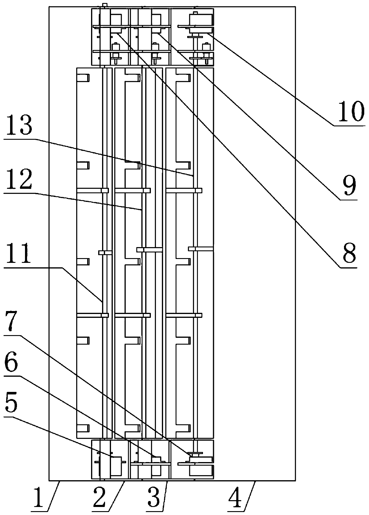
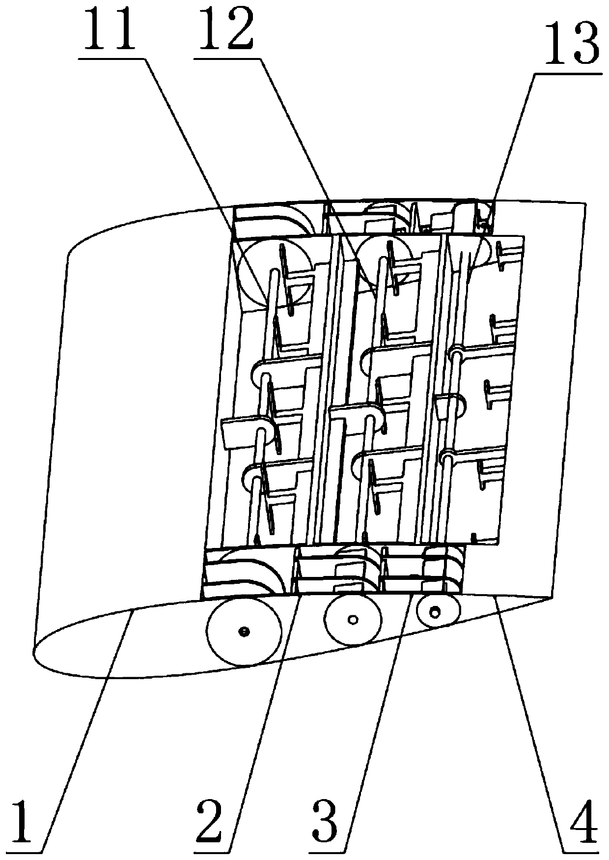
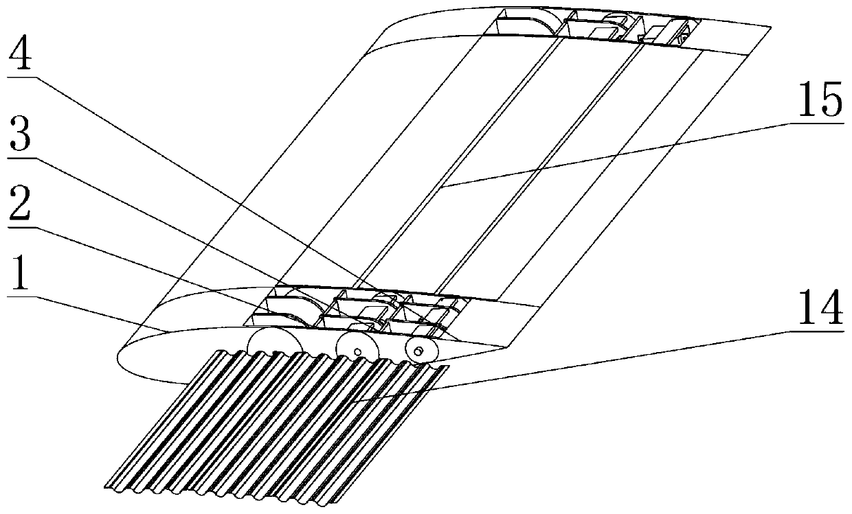
[0035] In order to solve the above-mentioned technical problems of the prior art, the inventor provides a deformed wing device, which includes four first to fourth wing sections 1, 2, 3, 4 made of laminates, the first to the fourth Six servos 5, 6, 7, 8, 9, 10, the outer diameter is The first to third shafts 11, 12, 13 made of aluminum, corrugated structure skin 14, rubber film skin 15, such as Figure 1-3 shown.

[0036] Such as Figure 4 As shown, the first wing section 1 is a fixed wing section, including a D-box 1.1 that supports the leading edge structure of the airfoil and improves the torsional rigidity, and eight lugs 1.2. Each lug 1.2 is marked with round hole. Such as Figure 5 As shown, the second wing section 2 is a movable section, including; T-beam structure 2.1, which is used to improve the bending stiffness of the wing; ten lugs 2.2, each of which has a The circular holes; 5 vertical bar-shaped supports 2.3 for connecting the corrugated skin to prevent...


PUM


Abstract

The invention provides an installation and use method of a corrugated plate skin for a variable-camber wing. According to the invention, the defects that the skin of the existing corrugated plate variable-camber wing cannot well maintain the airfoil profile, the continuity of the skin surface cannot be ensured, the driving load is difficult to load and the like are overcome. The variable-camber wing structure is composed of a variable-camber wing, a corrugated plate structure skin and the like, and the variable-camber wing drives a corresponding movable wing section to rotate through a steering engine so as to change the camber of the wing and the attack angle of relative incoming flow. The vertical strip-shaped supports on all the wing sections are connected with the corrugated structureskin, and collapse or separation of the skin is prevented. Compared with an existing deformed wing skin technology, the installation method of the corrugated plate skin for the variable-camber wing has the advantages that the smooth aerodynamic configuration surface of the deformed wing can be better maintained, aerodynamic force is borne, and therefore mechanical maneuverability is improved, aerodynamic performance is improved, and noise is lowered.

Description

technical field [0001] The invention relates to a deformable wing. Background technique [0002] Aircraft wing variable camber adaptive technology is to improve flight efficiency and maneuverability by adjusting the wing camber in real time according to changes in the flight environment and tasks during flight to adapt to complex and changeable mission environments. One of the main research directions for new technological breakthroughs. Although traditional wing control surfaces and high-lift devices can adjust the aerodynamic performance of the wing, they cannot provide a smooth and continuous aerodynamic surface due to the existence of hinge gaps. This discontinuity will cause the airflow on the wing surface to separate. The aerodynamic performance of the wing is reduced and the noise is increased. The variable camber wing can realize the smooth and continuous deformation of the wing camber, delay the separation of the airflow, and greatly improve the aerodynamic perfor...

Claims


Application Information

Patent Timeline
IPC IPC(8): B64C3/44B64C3/48
CPCB64C3/44B64C3/48
Inventor 谢长川白江波冒森申伟宏杨光昊安朝
Owner BEIHANG UNIV
Why Eureka
Try Eureka