Deforming foil structure for bridging curved fluid-dynamic surface

a fluid-dynamic surface and curved technology, applied in the direction of wing adjustment, etc., can solve the problems of linear deformation foils available to date, adopting the desired aerodynamic curvature, etc., and achieves the effect of reducing the number of deformation foils

Active Publication Date: 2021-01-07
NAT RES COUNCIL OF CANADA
View PDF0 Cites 1 Cited by
  • Summary
  • Abstract
  • Description
  • Claims
  • Application Information

AI Technical Summary

Benefits of technology

[0011]As far as known, the only deforming foils available to date are limited to linear (planar) actuation and incapable of adopting a desired aerodynamic curvature, or require skins that are independently stiff enough to resist fluid-dynamic load in use. At the very least, novel bridging structures that allows for design of higher curvature, and higher variability curvature, fluid-dynamic surfaces, are needed. Applicant has demonstrated a bridging structure for deforming foils that can be lighter weight, and use lower power articulation, or have higher extension, while resisting fluid-dynamic loads with a desired curved foil profile.
[0013]The resilient bodies may be leaf springs, coil or helical springs, or paired opposing springs having different rest separations. The resilient bodies may be webs, rods or wires composed of a same, similar or different material as the members, and may be monolithically joined by welding, fusion, adhesive or by extrusion, or may be joined mechanically. For mechanical joining, the resilient body may extend through a slit or opening in the members on a first facing sidewall, and couple to an end of an adjacent resilient body extending through a like slit or opening in the member of a second facing sidewall; or the resilient bodies may be coupled to the facing members at opposite ends. The webs, rods or wires may define a torturous serpentine path between pairs of facing sidewalls, such as a sinusoidal curve, or a composite of sinusoidal curves, may be non-symmetric, symmetric or antisymmetric, and may have a symmetric collection of zero crossings, such as a sinc curve. The webs, rods or wires may have a uniform thickness and width, or may have curvature, thickness, and width variations to produce a desired resilient force at each position of actuation, a desired longevity, and weight (critical for flight control surfaces but not all foils). An advantage of a web in the form of a ribbon is an increased stiffness of the member coupling relative to an equal thickness rod or wire, and a greater load distribution across the sidewalls, with simple manufacture. An advantage of a rod or wire is an ability to increase the extension range of the resilient body in a compact form, by bending the rod or wire in two degrees of freedom, and a wider variety of arrays of the rods / wires for engineered coupling stiffnesses of the members. While the resilient body may, for manufacturability, have curvature limited to a single plane, in some embodiments the resilient bodies may have a uniform or varying torsion. For example, even a ribbon of considerable width can have a uniformly spiraling path between the members; or a ribbon with a thickness running length-wise of the member at joining, may undergo a 90° twist near the edges such that for the remainder of the ribbon (intermediate the twists) only a ribbon thickness is presented in an orthogonal projection from the top surface of the members. This latter example may be provided at each alternate web with thicknesses and widths in this view. Furthermore, the slits or openings may alternate from length-wise to width-wise in adjacent members. Particularly each member may comprise an alternating sequence of length-wise and transverse slits, and adjacent members may have corresponding opposite or matching slits. Each resilient body may therefore have a same torsion, or a torsion that matches up to 180°. If the resilient body is a web or rod, it may have thickened edges, for tailored stiffness maps, and if a web, may have a longitudinal fold, thinning, or bend to increase stiffness.
[0015]The purpose of the bridging structure is to produce a curved fluid-dynamic suction or pressure surface extending between two rigid segments of a fluid-dynamic surface, such as a foil. One of the segments can be an edge segment, being a leading or trailing edge segment of the foil. Either segment may or not itself be an articulated, segmented or deforming segment of the foil, as long as a local part of the segments being joined is suitably rigid. The curved rail may, in principle, be affixed to only one of the edge and second segments, such as the second segment, but can be mounted at both ends to both segments, via an actuable linkage for allowing the motion of the edge segment with respect to the second segment. The curved rail may be extensible, like a single or multi-stage (in-line or parallel) drawer slider common in drawer hardware, and may further provide for a pivoting of a stage of the slider at one point in the actuation.
[0016]The rigid segments and bridging structure define at least one of a suction surface and a pressure surface for a foil. The rigid segments are preferably actuated by an actuator that is separate from the bridging structure, although the actuator may be built into, or share a stiffness support with the guide rails. The actuator preferably controls the motion of the rigid segments, and the bridging structure follows as a generally passive structure, with the elasticity provided by the resilience of the system being a lower order force. This lower order force, however, ensures that the members and resilient bodies move as a coordinated unit between relatively expanded and compact poses while prevent excessive pivoting of the members.

Problems solved by technology

As far as known, the only deforming foils available to date are limited to linear (planar) actuation and incapable of adopting a desired aerodynamic curvature, or require skins that are independently stiff enough to resist fluid-dynamic load in use.

Method used


Image

  • Deforming foil structure for bridging curved fluid-dynamic surface
  • Deforming foil structure for bridging curved fluid-dynamic surface
  • Deforming foil structure for bridging curved fluid-dynamic surface

Examples


example

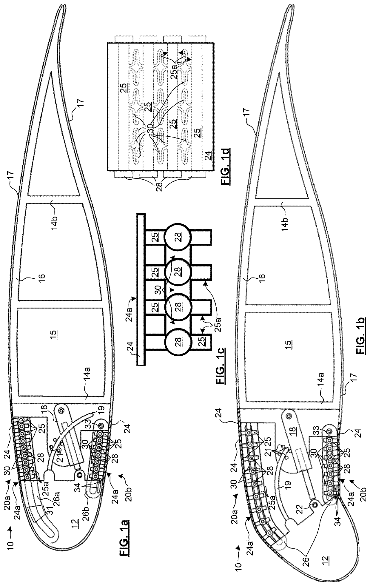
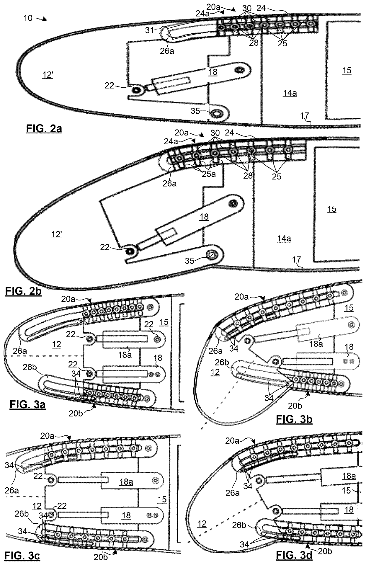
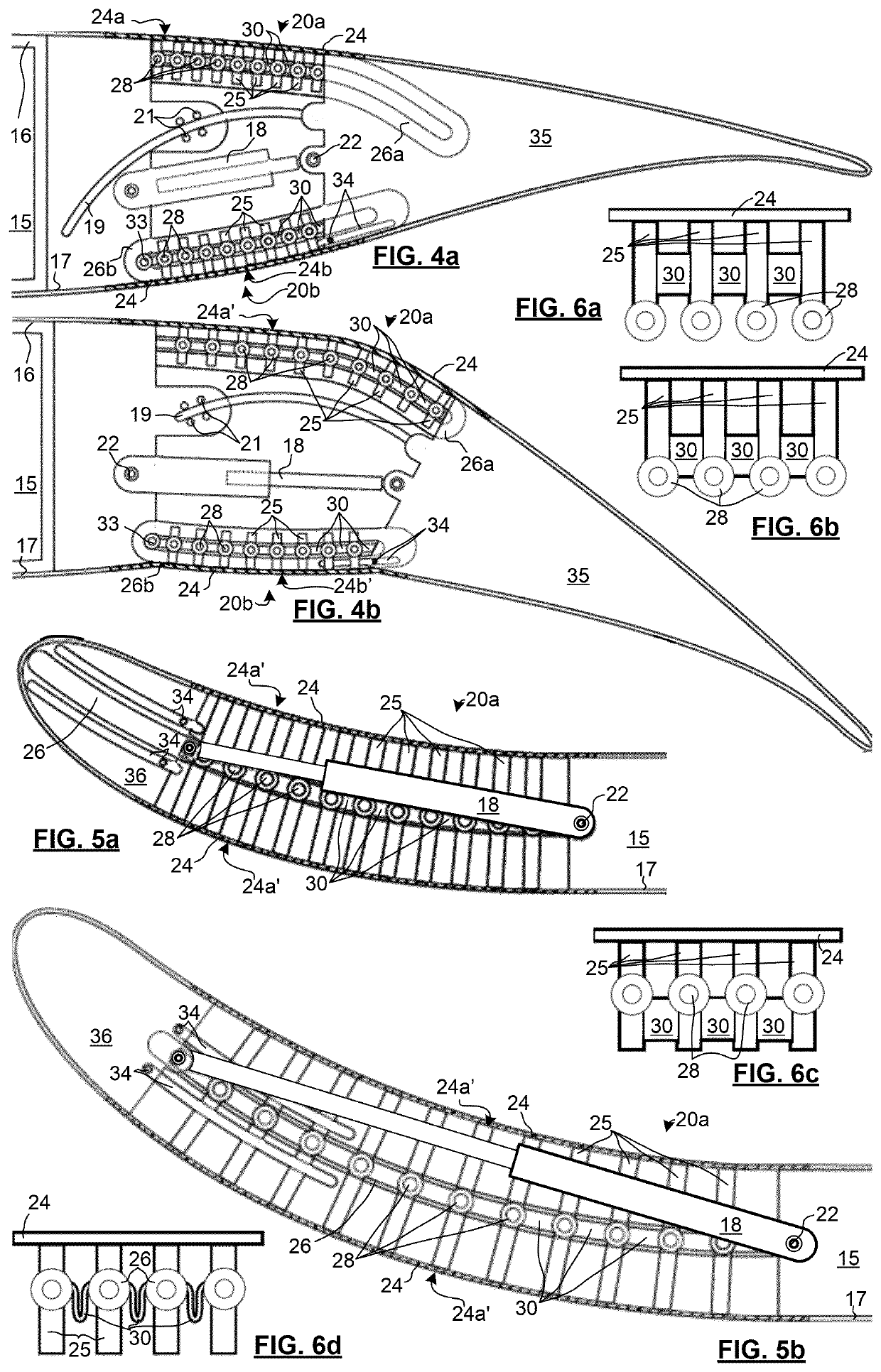
[0075]FIG. 7 is a side view of a 3-D printed bridging structure produced to test the present invention. The members 25 are substantially T shaped with an enlarged width at a bottom end thereof, and a small bifurcated tip for mounting to exposed ridges of an elastomeric sheet. The side view is of the sheet meeting a table on which it is resting.

[0076]The sheet was composed of E1040AL Urethane with 40 A Shore hardness. The ribbons and members were composed of LS Standard Nylon 12 GF with tensile modulus 2896 MPa-3585 MPa.

[0077]FIG. 8 shows the bridging structure from above. The ribbons are visible through the substantially transparent elastomeric sheet. To the left an enlargement is provided to facilitate view of the shapes of the resilient members, which are integrally formed with the members.

[0078]FIGS. 9a,b are images showing the bridging structure mounted to a test rig, in closed and opened poses. A rigid leading edge segment that corresponds to 12 in FIG. 1 is provided made of al...


PUM


Abstract

A bridging structure for a deforming foil, such as a morphing wing, that provides a fluid-dynamic surface throughout foil deformation that forms a curved fluid-dynamic surface with a relatively low drag. A high extent of foil deformation can be provided, with lower actuation force, providing a fluid-dynamic surface with a simple or complex curve in one direction, by providing a set of rail-mounted members that are joined at one end to a deforming sheet. By coupling the members with high elongation, resilient bodies, adjacent members can support each other, while permitting extension, and accommodating curvature.

Description

CROSS-REFERENCE TO RELATED APPLICATIONS[0001]This application claims the benefit of Canadian Patent Application Serial No. 3,048,431 filed Jul. 3, 2019.FIELD OF THE INVENTION[0002]The present invention relates in general to a bridging structure for a deforming foil, that provides a fluid-dynamic surface throughout foil deformation; and in particular to an articulated bridging structure that is extendable to fill gaps between separated foil segments producing the fluid-dynamic surface with variable curvature in one direction.BACKGROUND OF THE INVENTION[0003]Noise generated through aeroacoustics is a known problem with commercial aviation. The noise is unfortunately greatest when it is least welcome: on landing and take-off. This is because of leading and trailing edge structures that are required to be extended to generate higher lift during lower velocity flight. These leading and trailing edge structures conventionally are “slotted”, which is to say that an open space extends betwe...

Claims


Application Information

Patent Timeline
Patent Type & Authority Applications(United States)
IPC IPC(8): B64C3/48
CPCB64C3/48B64C2003/445B64C3/50B64U30/12
Inventor MANGIONE, JAYEFEREIDOONI, AMINCHEN, YONGWICKRAMASINGHE, VIRESHMARCHWICA, JAN
Owner NAT RES COUNCIL OF CANADA
Why Eureka
Try Eureka