Multi-mode conversion micro-miniature unmanned aerial vehicle

A drone and miniature technology, applied in the field of bionic aircraft, can solve the problems of low aerodynamic control efficiency, excessive energy, consumption, etc., and achieve the effect of simple structure, easy control, and light weight

Inactive Publication Date: 2021-08-06
BEIJING INSTITUTE OF TECHNOLOGYGY
View PDF7 Cites 2 Cited by
  • Summary
  • Abstract
  • Description
  • Claims
  • Application Information

AI Technical Summary

Problems solved by technology

Fixed-wing MAVs have obvious advantages in high-speed long-distance cruise flight, but cannot achieve hovering and low-speed flight; rotor MAVs have the ability to hover and low-speed flight, but need additional devices to overcome anti-torque problems
In addition, both fixed-wing and rotary-wing MAVs face the problem of significantly reduced aerodynamic force and control efficiency at low Reynolds numbers
Flapping wing MAV can generate enough lift at low Reynolds number, but it needs to consume more energy; at the same time, the mechanism of flapping wing generating lift is complicated, and it is difficult to design the mechanical structure in practical applications
These all restrict the design, manufacture and application of flapping wing MAV

Method used


Image

  • Multi-mode conversion micro-miniature unmanned aerial vehicle
  • Multi-mode conversion micro-miniature unmanned aerial vehicle
  • Multi-mode conversion micro-miniature unmanned aerial vehicle

Examples


Embodiment Construction

[0030] The present invention will be described in detail below with reference to the accompanying drawings and examples.

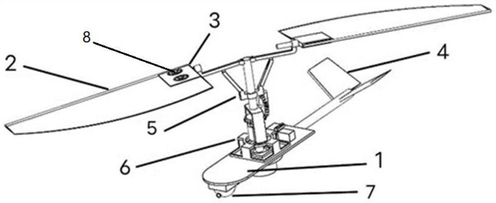
[0031] The invention provides a multi-mode conversion micro-miniature unmanned aerial vehicle, such as figure 1 As shown, it includes a fuselage 1, a deformable wing 2, a wing flapping system 5, a main shaft 10, a main shaft rotation control system 6, an empennage 4 and a reconnaissance system 7.

[0032] The deformable wing 2 adopts a shape memory alloy with two-way memory effect, and the deformable wing 2 is a hollow structure with a heating device and a cooling device inside; a temperature control device 8 is provided at the root of the deformable wing 2 for adjusting The heating power of the heating device.

[0033] The main shaft 10 is vertically installed at the center of gravity of the fuselage 1, and the deformable wings 2 are distributed on both sides of the top of the main shaft 10 and flutter up and down through the wing flapping system 5; fi...


PUM


Abstract

The invention discloses a multi-mode conversion micro-miniature unmanned aerial vehicle which comprises a fuselage, deformable wings, a wing flapping system, a main shaft, a main shaft rotation control system and an empennage. The main shaft is vertically installed at the gravity center position of the fuselage through the main shaft rotation control system, and the deformable wings are distributed on the two sides of the top end of the main shaft and flap up and down through the wing flapping system. The empennage is mounted at the tail of the fuselage; when the deformable wings on the two sides are of a central symmetry structure, a flapping rotor wing mode is formed, and the main shaft rotates under the control of the main shaft rotation control system; the deformable wings are in an axial symmetry structure to form a flapping wing mode after being deformed, and the main shaft stops rotating under the control of the main shaft rotation control system. According to the invention, vertical take-off and landing, spot hovering and rapid take-off can be realized.

Description

technical field [0001] The invention relates to the technical field of bionic aircraft, in particular to a multi-mode conversion miniature unmanned aerial vehicle. Background technique [0002] At present, micro-aircraft in various countries are in the stage of development but fewer finished products. The main role of micro-UAVs is to perform reconnaissance, detection, and intelligence acquisition tasks in some small places, which has a relatively large advantage over traditional UAVs. [0003] The three typical MAV layout forms at the present stage have their own characteristics and advantages, but their shortcomings are also obvious. Fixed-wing MAVs have obvious advantages in high-speed long-range cruise flight, but cannot achieve hovering and low-speed flight; rotor MAVs have hovering and low-speed flight capabilities, but require additional devices to overcome anti-torque problems. In addition, both fixed-wing and rotary-wing MAVs face the problem of significantly redu...

Claims


Application Information

Patent Timeline
Patent Type & Authority Applications(China)
IPC IPC(8): B64C37/00B64C33/02B64C27/06B64C5/00B64D27/24B64D35/00
CPCB64C37/00B64C33/02B64C27/06B64C5/00B64D27/24B64D35/00B64U10/00B64U50/19
Inventor 高文萱赵宇辰费潇永高帆吴炎烜赵新悦杜宏宝
Owner BEIJING INSTITUTE OF TECHNOLOGYGY
Why Eureka
Try Eureka