Supercharge Your Innovation With Domain-Expert AI Agents!

Solar cell array driving mechanism

A solar cell array and drive mechanism technology, applied in the field of solar cell arrays, can solve the problems of high research and development costs, and achieve the effect of reducing the development cycle and cost

Active Publication Date: 2020-05-08
INNOVATION ACAD FOR MICROSATELLITES OF CAS +1
View PDF22 Cites 0 Cited by
  • Summary
  • Abstract
  • Description
  • Claims
  • Application Information

AI Technical Summary

Problems solved by technology

[0004] The purpose of the present invention is to provide a solar cell array driving mechanism to solve the problem of high research and development costs of the existing traditional driving mechanism

Method used


Image

  • Solar cell array driving mechanism
  • Solar cell array driving mechanism
  • Solar cell array driving mechanism

Examples


Embodiment 1

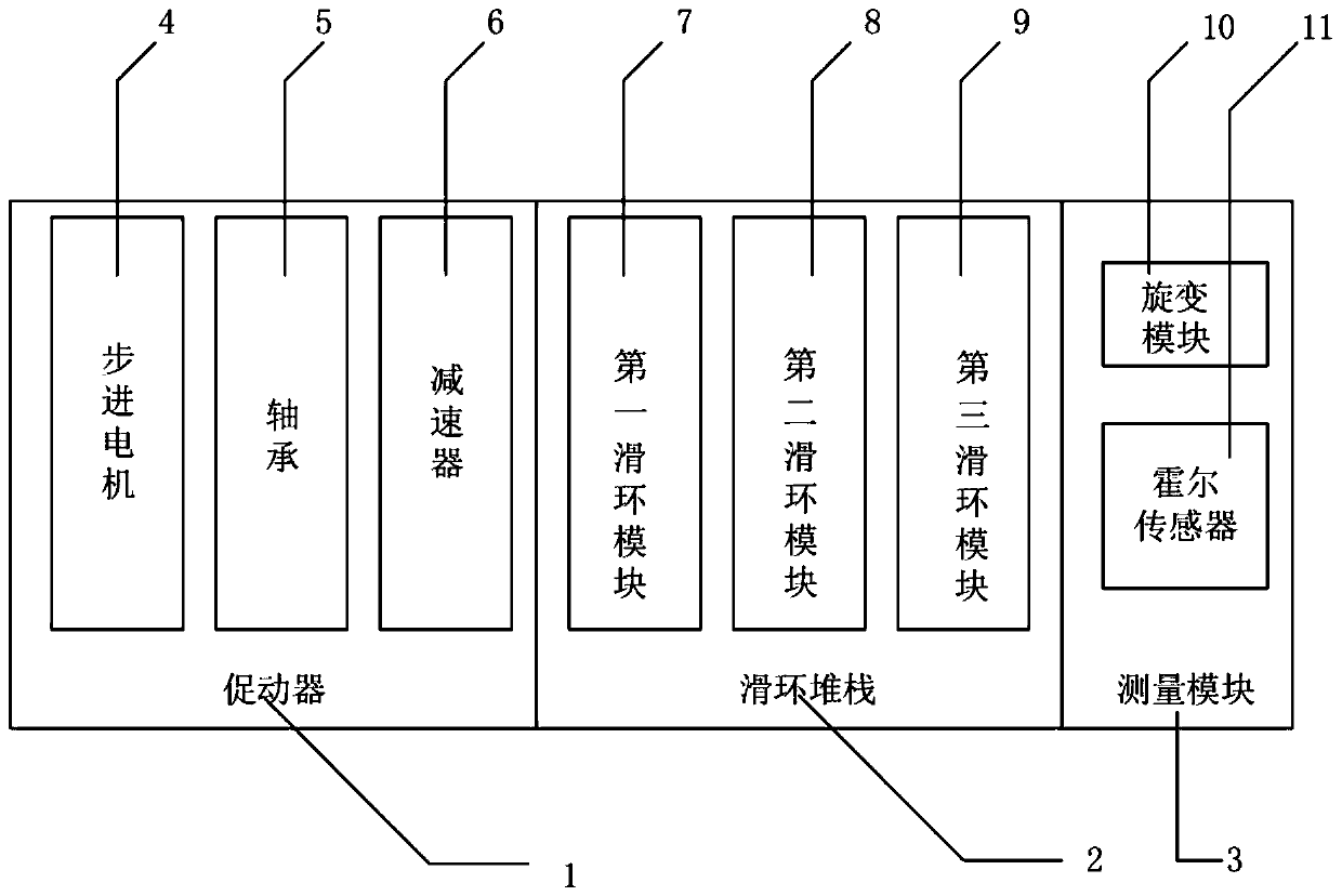
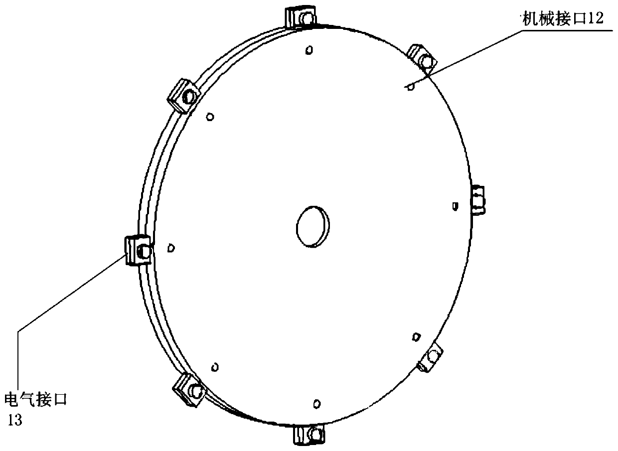
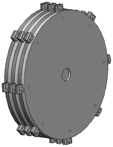
[0030] This embodiment provides a solar cell array driving mechanism, such as Figure 1~3 As shown, the solar array driving mechanism is used to provide driving and transmission functions for the solar array, and the solar array driving mechanism includes an actuator 1, a slip ring stack 2 and a measurement module 3, wherein: the actuator The actuator 1 is used to provide a driving function for the solar cell array, and the measurement module 3 is used to measure the motion state of the solar cell array; the solar cell array includes electrical components of the solar cell array, and the slip ring stack 2 outputs The electrical connector of the shaft section is electrically connected to the electrical components of the solar cell array, and the power output by the electrical components of the solar cell array is transmitted to the satellite body through the slip ring stack 2; the slip ring stack 2 includes a plurality of slip rings. Ring module (e.g. figure 1 As shown, the slip ...


PUM


Abstract

The invention provides a solar cell array driving mechanism. The solar cell array driving mechanism is used for providing a driving function and a transmission function for a solar cell array, the solar cell array driving mechanism comprises an actuator, a slip ring stack and a measurement module, the actuator is used for providing the driving function for the solar cell array, and the measurementmodule is used for measuring the motion state of the solar cell array; the solar cell array comprises a solar cell array electrical assembly, the slip ring stack is electrically connected with the solar cell array electrical assembly through an electrical connector of an output shaft section, and power output by the solar cell array electrical assembly is transmitted to the satellite body throughthe slip ring stack. The slip ring stack comprises a plurality of slip ring modules, all the slip ring modules are connected through mechanical interfaces, and the number of the slip ring modules isincreased or decreased according to different task requirements so as to achieve the transmission function of different powers of the solar cell array electrical assembly.

Description

Technical field [0001] The invention relates to the technical field of solar cell arrays, in particular to a solar cell array driving mechanism. Background technique [0002] Solar arrays are also called solar panels, which are satellite energy stand-alone machines and are responsible for the power supply of satellites. For a three-axis stabilized satellite, the solar windsurfing board needs to drive the windsurfing board to orient to the sun through a driving mechanism to maximize energy acquisition. The electric energy obtained by the solar windsurfing board needs to be transmitted to the satellite through the slip ring of the driving mechanism. [0003] However, for different space missions, satellites have different energy requirements. Therefore, for the driving mechanism, it is necessary to design slip ring components of different specifications for different missions. In the general spacecraft single-machine development process, the custom development of a new product needs...

Claims


Application Information

Patent Timeline
Patent Type & Authority Applications(China)
IPC IPC(8): B64G1/44
CPCB64G1/443
Inventor 解放林宝军蒋桂忠沈苑安洋季毅巍陈鸿程陈良屹
Owner INNOVATION ACAD FOR MICROSATELLITES OF CAS
Features
  • R&D
  • Intellectual Property
  • Life Sciences
  • Materials
  • Tech Scout
  • Unparalleled Data Quality
  • Higher Quality Content
  • 60% Fewer Hallucinations
Learn More