
High-speed railway expansive rock soil deep cutting structure and construction method thereof

A technology of high-speed railways and expansive rocks, applied in infrastructure engineering, roads, buildings, etc., to achieve the effects of controllable stability, favorable promotion and application, and small arching force

Pending Publication Date: 2020-05-08
CHINA RAILWAY ERYUAN ENG GRP CO LTD
View PDF0 Cites 3 Cited by
  • Summary
  • Abstract
  • Description
  • Claims
  • Application Information

AI Technical Summary

Problems solved by technology

[0003] The purpose of the present invention is to: aim at the problems existing in the prior art, provide a high-speed railway expansive rock-soil deep cutting structure and construction method, which can effectively solve the technical problems of high-speed railway expansive rock-soil deep cutting stability control and realization of arch deformation control

Method used


Image

  • High-speed railway expansive rock soil deep cutting structure and construction method thereof
  • High-speed railway expansive rock soil deep cutting structure and construction method thereof
  • High-speed railway expansive rock soil deep cutting structure and construction method thereof

Examples


Embodiment 1

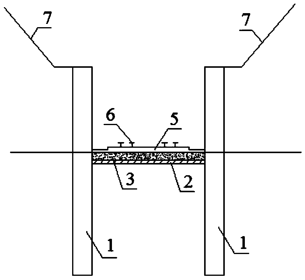
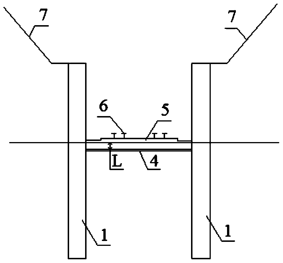
[0045] Such as Figure 1-2 Shown, a kind of high-speed railway expansive rock-soil deep cutting structure of the present invention comprises:

[0046]A plurality of reinforcement support piles 1 are divided into two rows and arranged symmetrically at the foot of the deep road cutting slope. The reinforcement support piles 1 in each row are arranged at intervals, and the distance between two adjacent reinforcement support piles 1 in each row of the reinforcement support piles 1 is 5m-7m:

[0047] The support beam 3 is arranged on the foundation between the two symmetrically arranged reinforced support piles 1, and the bottom of the support beam 3 is provided with water holes at intervals, and the water holes are arranged in an upper concave shape. The section of the water hole is semicircular, rectangular, triangular or trapezoidal, and the width of the water hole is 0.1m-0.2m;

[0048] The buffer layer 2 is arranged on the foundation at the bottom of the support beam 3, and ...

Embodiment 2

[0054] Such as Figure 1-2 As shown, a kind of construction method of high-speed railway expansive rock-soil deep cutting structure as described in embodiment 1 of the present invention, comprises the following steps:

[0055] A. Excavate the expansive rock-soil slope layer by layer from top to bottom, and reinforce and protect the excavated slope 7 layer by layer until the top elevation of the reinforced support pile 1 is set;

[0056] B. The pile well of the reinforced support pile 1 is constructed at intervals, at the position where the support beam 3 and the bearing plate 5 are arranged, the steel bars of the support beam 3 of different lengths are pre-embedded outwards through the pile well and the 5 steel bars of the bearing plate, the length is 1m-3m;

[0057] C, setting the reinforced support pile 1 reinforcement cage, the reinforcement support pile 1 reinforcement cage is respectively fixedly connected with the 3 reinforcement bars of the support beam and the 5 reinf...


PUM


Abstract

The invention discloses a high-speed railway expansive rock soil deep cutting structure and a construction method thereof. The structure comprises: a plurality of reinforcing support piles, wherein the reinforcing support piles are divided into two rows and are symmetrically arranged at a deep cutting slope toe, and each row of reinforcing support piles are arranged at intervals; supporting crossbeams which is arranged on a foundation between the two reinforcing supporting piles which are symmetrically arranged; a buffer layer which is arranged on the foundation at the bottoms of the supporting cross beams; a waterproof layer which is arranged on a foundation between every two adjacent supporting cross beams; and a bearing plate which is connected to the tops of the supporting cross beamsand connected to the reinforcing supporting piles, wherein the bearing plate is used for arranging a rail structure. The technical problem of upwarp deformation of the high-speed railway caused by expansive rock and soil is effectively solved, and the high-speed railway expansive rock soil deep cutting structure has the characteristics of expansive rock and soil stability, controllable upwarp deformation, convenience in construction, economy, environmental protection, convenience in popularization and application and the like.

Description

technical field [0001] The invention relates to the field of geotechnical engineering, in particular to a high-speed railway expansive rock-soil deep cutting structure and a construction method. Background technique [0002] Expansive rocks and soils are widely distributed in my country. Expansive rocks and soils have the characteristics of water absorption swelling, water loss shrinkage, repeated expansion and contraction deformation, and sharp attenuation of water soaking strength. It is known as "cancer" in the field of geotechnical engineering. When high-speed railways, especially ballastless track high-speed railways, pass through expansive rock and soil foundations in the form of deep cuttings, its stability and "millimeter-level" deformation control is difficult, especially the repair of ballastless track arch deformation caused by expansive rock and soil is extremely difficult and inefficient , High cost. With the continuous advancement of the construction of high-s...

Claims


Application Information

Patent Timeline
Patent Type & Authority Applications(China)
IPC IPC(8): E01B2/00E02D17/20
CPCE01B2/00E02D17/20E02D17/207
Inventor 姚裕春袁碧玉陈伟志封志军高继涛
Owner CHINA RAILWAY ERYUAN ENG GRP CO LTD
Learn More