Hydraulic locking cushion valve, hydraulic system and land leveler

A technology of hydraulic lock and buffer valve, which is applied in the field of hydraulic buffer, can solve the problems of high cost, difficult maintenance and installation arrangement, etc., and achieve the effect of easy maintenance or installation and cost reduction

Inactive Publication Date: 2020-05-08
GUANGXI LIUGONG MASCH CO LTD
View PDF11 Cites 0 Cited by
  • Summary
  • Abstract
  • Description
  • Claims
  • Application Information

AI Technical Summary

Problems solved by technology

[0005] The technical problem to be solved by the present invention is to provide a hydraulic lock buffer valve, a hydraulic system for the problems of high cost, difficult maintenance, installation and arrangement caused by using an accumulator to buffer the impact of the existing grader blade lifting hydraulic system. And grader, so as to achieve blade buffer and avoid maintenance and installation difficult and high cost

Method used


Image

  • Hydraulic locking cushion valve, hydraulic system and land leveler
  • Hydraulic locking cushion valve, hydraulic system and land leveler
  • Hydraulic locking cushion valve, hydraulic system and land leveler

Examples


Embodiment Construction

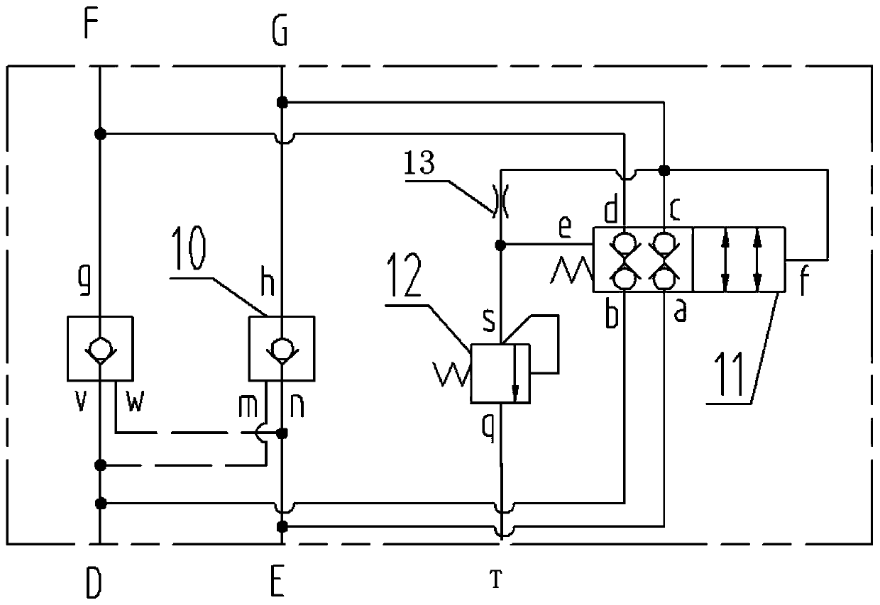
[0018] The specific implementation will be described below in conjunction with the accompanying drawings.

[0019] Such as figure 1 As shown, the hydraulic lock buffer valve in this embodiment has D port, E port, F port, G port, T port, and includes hydraulic lock valve 10, on-off valve 11, throttle valve 13. Overflow valve 12.

[0020] The hydraulic lock valve 10 is a two-way hydraulic lock valve. When the D oil port has high-pressure oil input, the D oil port to the F oil port are forward-conducted through the check valve of the oil circuit, and the high-pressure oil at the D oil port controls the E oil. The control port m of the one-way valve between the port and the G oil port makes it conduct in reverse. In the same way, when the E port has high-pressure oil input, the E port to the G port is forward-conducted through the check valve of the oil circuit, and the high-pressure oil at the E port controls the one-way flow between the D port and the F port. To the control e...


PUM


Abstract

The invention relates to land leveler hydraulic systems and provides a hydraulic locking cushion valve, a hydraulic system comprising the same and a land leveler in order to solve the problems that anexisting land leveler shovel blade lifting hydraulic system buffers impact through an energy accumulator, and the cost is high and maintenance and installation arrangement are difficult. According tothe hydraulic locking cushion valve, the hydraulic system comprising the same and the land leveler provided by the invention, an oil port D and an oil port E of the hydraulic locking cushion valve communicate with an oil port F and an oil port G through hydraulic lock valves in the forward direction correspondingly. An oil port of a switching valve is connected with the oil port G, an oil port aof the switching valve communicates with or cut off with and oil port c, the oil port c of the switching valve communicates with the oil port a, and the oil port c communicates with an oil tank when areversing valve is in a neutral position. The oil port G of the hydraulic lock valve is connected with the control end of the switching valve, and the oil port G is connected with an oil port T through a throttle valve and an overflow valve. A switching valve spring cavity is connected between the throttle valve and the overflow valve. The hydraulic locking cushion valve is applied to the land leveler shovel blade lifting hydraulic system and can achieve the shovel blade impact buffering function without the energy accumulator, a solenoid valve and other elements. Accordingly, the cost is reduced, and the hydraulic locking cushion valve is convenient to maintain or install.

Description

technical field [0001] The invention relates to a hydraulic buffer technology, more specifically, to a hydraulic lock buffer valve, a hydraulic system and a grader. Background technique [0002] The shovel is an important working device of the grader, and the height of the shovel is adjusted by the shovel lifting cylinder. Existing grader blade lift hydraulic system is generally made up of elements such as pump, reversing valve, hydraulic lock valve and oil tank, lifting oil cylinder. When the height of the shovel is not adjusted, the hydraulic lock valve cuts off the oil passages in and out of the large cavity and the small cavity of the lift cylinder to prevent the shovel from fluctuating up and down during operation. [0003] However, when the shovel encounters an excessive impact, it may cause damage to the hydraulic pipeline, hydraulic cylinder, and valve. In order to reduce the impact of the lifting cylinder during work, the hydraulic system will add an accumulator a...

Claims


Application Information

Patent Timeline
Patent Type & Authority Applications(China)
IPC IPC(8): F15B11/17F15B21/00F15B11/00F15B13/01E02F3/815E02F3/85
CPCE02F3/84F15B11/003F15B11/17F15B13/01F15B21/008
Inventor 李良周刘光喜白健信李大尤卢南潮
Owner GUANGXI LIUGONG MASCH CO LTD
Why Eureka
Try Eureka