Eureka AIR delivers breakthrough ideas for toughest innovation challenges, trusted by R&D personnel around the world.

A solenoid valve pressure buffer device and pressure buffer method

A technology of buffering device and buffering method, which is applied in the direction of fluid pressure actuating device, valve device, valve operation/release device, etc., which can solve the fluctuation of output oil pressure, affect the quality of shifting, and the influence of output pressure of electro-hydraulic control circuit, etc. problem, to achieve the effect of improving stability and wide applicability

Active Publication Date: 2021-01-01
BEIJING INSTITUTE OF TECHNOLOGYGY
View PDF8 Cites 0 Cited by
  • Summary
  • Abstract
  • Description
  • Claims
  • Application Information

AI Technical Summary

Problems solved by technology

[0005] In view of the above analysis, the present invention aims to provide a solenoid valve pressure buffer device and a pressure buffer method to solve the problem that the output oil pressure of the existing solenoid valve will fluctuate. If the oil pressure fluctuation cannot be reduced or eliminated, it will affect the electrohydraulic The output pressure of the control circuit will affect the quality of shifting, and even affect the service life of the clutch

Method used


Image

  • A solenoid valve pressure buffer device and pressure buffer method
  • A solenoid valve pressure buffer device and pressure buffer method
  • A solenoid valve pressure buffer device and pressure buffer method

Examples


Embodiment 1

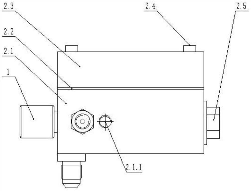
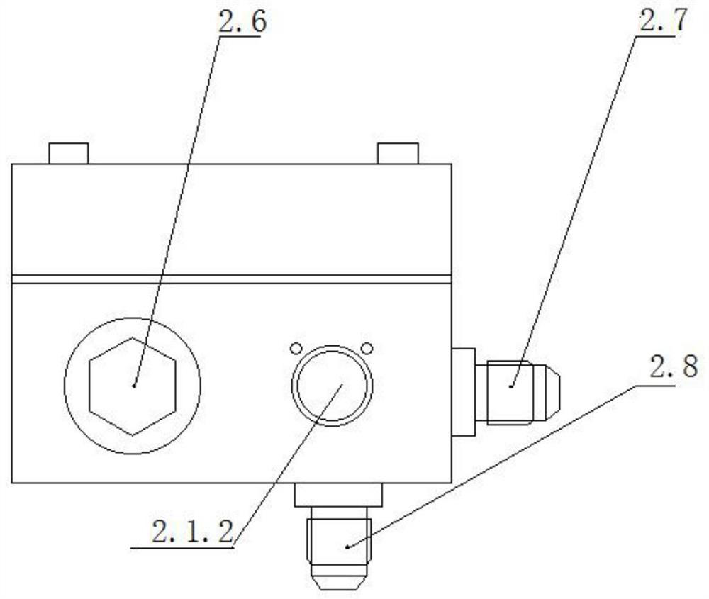
[0041]A specific embodiment of the present invention discloses a solenoid valve pressure buffer device, which includes an upper valve cover 2.3, a steel gasket 2.2 and a lower valve cover 2.1.

[0042]figure 2 It is a schematic diagram of the structure of the pressure buffer device 2 of the present invention. Specifically, the upper valve cover 2.3, the steel gasket 2.2 and the lower valve cover 2.1 are arranged in order from top to bottom to form the solenoid valve pressure buffer device of the present invention, and the upper valve cover 2.3, the steel gasket 2.2 and the lower valve cover The valve covers 2.1 are fixed as a whole by the first bolt 2.4, such asfigure 2 Shown.

[0043]In other words, the first bolt 2.4 passes through the upper valve cover 2.3, the steel gasket 2.2 and the lower valve cover 2.1 in turn, and the upper valve cover 2.3, the steel gasket 2.2 and the lower valve cover 2.1 are fixed by tightening and fixing the first bolt 2.4. One.

[0044]Further, the first bolt 2...

Embodiment 2

[0070]The shape of the damping oil passage 2.3.1 in the first embodiment can be linear or asFigure 6The bent shape shown.

[0071]Alternatively, the damping oil passage 2.3.1 is designed to be T-shaped and has three divided oil passages, including a first damping oil passage, a second damping oil passage and a third damping oil passage. Wherein, the two ends of the first damping oil passage and the second damping oil passage are respectively communicated with the first damping hole 2.2.1 and the second damping hole 2.2.2 to realize the communication with the solenoid valve 1 and the accumulator. The end of the third damping oil passage is used as the movable end, and a movable sliding block seal is provided. The movable sliding block can move in the third damping oil passage of the damping oil passage 2.3.1, adjust the length of the damping oil passage 2.3.1, and finally realize the The adjustment of the damping pressure buffer effect of the damping oil passage 2.3.1 enables the pressu...

Embodiment 3

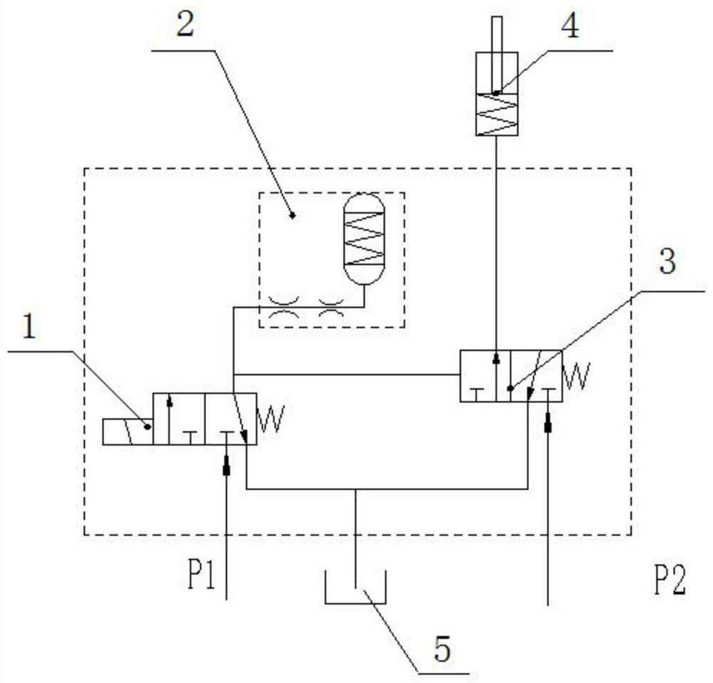
[0073]This embodiment provides a pressure buffering method. The solenoid valve pressure buffering device of the first embodiment is used. When the solenoid valve 1 is working, the oil will enter the damping oil passage 2.3.1 through the first orifice 2.2.1, and then through the first orifice 2.2.1. The second orifice 2.2.2 enters the accumulator. As the oil pressure increases, the spring 2.9 in the accumulator will be compressed by the spool 2.10 and pass through the first orifice 2.2.1 and the damping oil passage 2.3. 1. The second orifice 2.2.2 and the accumulator perform pressure buffering; when the solenoid valve is de-energized, the oil in the accumulator is discharged first and flows back to the tank 5 from the oil discharge port of the solenoid valve 1. During the test, a pressure sensor can be installed to test the pressure change in the working cavity.

[0074]When the solenoid valve 1 works, the pressure buffer process of the buffer device is:

[0075]1) Solenoid valve 1 is inst...


PUM


Abstract

The invention relates to an electromagnetic valve pressure buffering device and a pressure buffering method, belongs to the field of transmission electro-hydraulic control. The problem of fluctuationof output oil pressure of an electromagnetic valve caused by influence of the electromagnetic valve or an external environment in the prior art is solved. The buffering device comprises an upper valvedeck, a lower valve deck and a steel gasket between the upper valve deck and the lower valve deck; and two damping holes are formed in the steel gasket, the electromagnetic valve is arranged on the lower valve deck, hydraulic oil flowing out of an oil outlet of the electromagnetic valve flows into a damping oil channel of the upper valve deck through the first damping hole and flows back into anenergy accumulator in the lower valve deck through the second damping hole, a valve element of the energy accumulator pushes a spring in the energy accumulator to be compressed, and the damping oil channel and the energy accumulator form a buffering branch to be connected with a load branch in parallel to buffer the fluctuation of the output oil pressure of the electromagnetic valve. According tothe buffering device, when hydraulic oil input into the electromagnetic valve generates pressure fluctuation, buffering adjustment of fluctuant oil pressure can be achieved, so that the stability of asystem is kept.

Description

Technical field[0001]The invention relates to the technical field of electro-hydraulic control circuits, and in particular to a solenoid valve pressure buffer device and a pressure buffer method.Background technique[0002]At present, whether it is a hydromechanical automatic transmission or a dual-clutch automatic transmission, the coupling or disengagement of the clutch / brake is achieved through electro-hydraulic control. Some clutches / brakes use a solenoid valve direct-acting electro-hydraulic control circuit, and some use a solenoid valve as a pilot control valve.[0003]No matter what kind of electro-hydraulic control circuit, when the solenoid valve is affected by itself or the external environment, the output oil pressure of the solenoid valve will fluctuate. If the oil pressure fluctuation cannot be reduced or eliminated, the output pressure of the electro-hydraulic control circuit will be affected. This will affect the quality of shifting and even affect the service life of the...

Claims


Application Information

Patent Timeline
Patent Type & Authority Patents(China)
IPC IPC(8): F16K31/06F15B1/02F16H61/30
CPCF15B1/021F16H61/2807F16H61/30F16K31/06
Inventor 席军强任延飞陈慧岩
Owner BEIJING INSTITUTE OF TECHNOLOGYGY
Why Eureka
Eureka Blog
Learn More