Tail gas switching peak value purification device with heat accumulating type incinerator

A purification device and incinerator technology, applied in incinerators, lighting and heating equipment, combustion methods, etc., can solve the problems of system stability and pressure fluctuations, and achieve the effect of small pressure fluctuations

Active Publication Date: 2014-08-06
JG ENVIRONMENTAL TECH
View PDF9 Cites 4 Cited by
  • Summary
  • Abstract
  • Description
  • Claims
  • Application Information

AI Technical Summary

Problems solved by technology

However, although it can solve the problem of pipeline and control valve flow design, there are problems of system stability and pressure fluctuation.

Method used


Image

  • Tail gas switching peak value purification device with heat accumulating type incinerator
  • Tail gas switching peak value purification device with heat accumulating type incinerator
  • Tail gas switching peak value purification device with heat accumulating type incinerator

Examples


Embodiment Construction

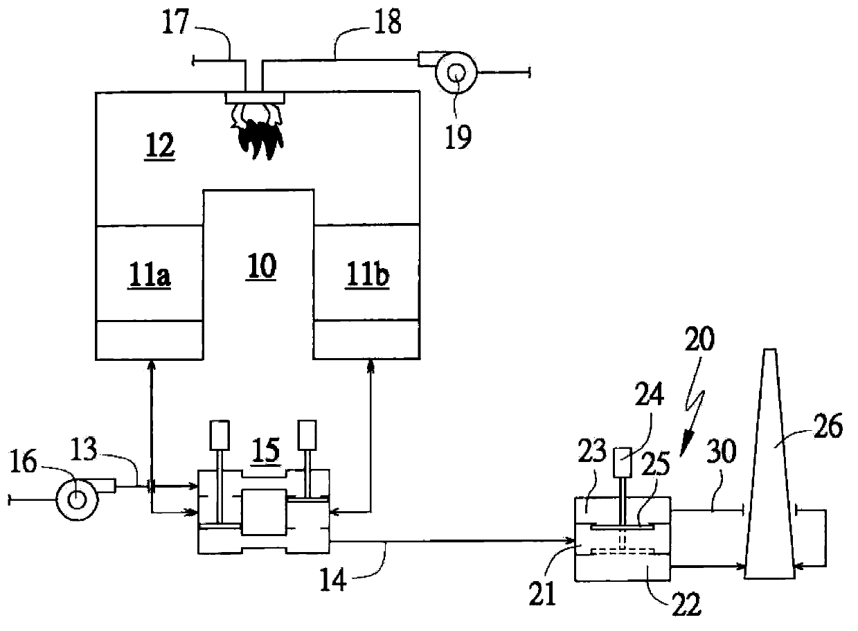
[0041] First, see figure 2 As shown, the first embodiment of the present invention includes: a regenerative incinerator 10 with at least a first regenerator 11a, a second regenerator 11b, and a combustion chamber 12 inside, and an exhaust gas inlet pipe is connected to the outside 13. The exhaust pipe 14, the fuel pipe 17 and the gas intake pipe 18, and the exhaust gas intake pipe 13 and the exhaust pipe 14 are provided with a flow direction control valve 15 which controls the flow of air to be incinerated from the exhaust gas. The air pipe 13 enters the first regenerator 11a (or the second regenerator 11b), and the air flow after incineration is controlled to enter the exhaust pipe 14 through the second regenerator 11b (or the first regenerator 11a). The exhaust gas intake pipe 13 is provided with an exhaust gas intake fan 16, and the combustion gas intake pipe 18 is provided with a combustion gas intake fan 19; a poppet valve (poppet valve) 20 is separated from the intake con...


PUM


Abstract

The invention relates to a tail gas switching peak value purification device with a heat accumulating type incinerator, which comprises the heat accumulating type incinerator and a poppet valve, wherein the inside of the heat accumulating type incinerator is partitioned into a first heat accumulating chamber, a second heat accumulating chamber and a combustion chamber at least, the outside of the heat accumulating type incinerator is connected with a waste gas inlet pipe and an exhaust pipe, and both the inlet pipe and the exhaust pipe are provided with flow control valves; the poppet valve is partitioned into a gas inlet layer connected with the exhaust pipe, a purified gas outlet layer connected with an exhaust chimney and an unpurified gas outlet layer connected with a buffering pipe body, and the lifting of an internal disc is controlled by a drive part to switch airflow to flow out from the purified gas outlet layer or the unpurified gas outlet layer; the other end of the buffering pipe body is connected with the exhaust chimney; the total volume of the buffering pipe body and the unpurified gas outlet layer cannot be smaller than the volume of unpurified gas retained in the heat accumulating chambers and the flow control valve. The tail gas switching peak value purification device has the efficacies of small pressure variation, stable system, less odor, simple structure and space saving.

Description

Technical field [0001] The invention relates to a regenerative incinerator tail gas switching peak purification device, in particular to a lift valve that controls the flow direction of the air flow after incineration in the incinerator, and is directly connected to the exhaust chimney and the outer valve of the incinerator. The air outlet layer is connected to the design of the buffer tube body. Background technique [0002] Organic solvents widely used in life and production are easily volatile into gases at room temperature, so they are also called Volatile Organic Compounds (VOCs). Most VOCs are toxic to the human body and must be treated. However, the incineration method is one of the VOCs waste gas treatment methods. Under appropriate conditions, the VOCs removal rate can reach 90-99%. The products after combustion are usually water, carbon dioxide, nitrogen oxides, sulfur oxides, etc. A method that can effectively treat the VOCs and odor contained in the exhaust gas; but ...

Claims


Application Information

Patent Timeline
Patent Type & Authority Applications(China)
IPC IPC(8): F23G7/06
Inventor 张丰堂
Owner JG ENVIRONMENTAL TECH
Why Eureka
Try Eureka