Panoramic image splicing method in airport environment

A panoramic image and image technology, which is applied in the field of image processing, can solve the problems that the image content of the stitching algorithm is greatly affected, the price of special imaging equipment is expensive, and it is impossible to obtain a better stitching effect.

Active Publication Date: 2020-05-08
NANJING LES ELECTRONICS EQUIP CO LTD
View PDF3 Cites 11 Cited by
  • Summary
  • Abstract
  • Description
  • Claims
  • Application Information

AI Technical Summary

Problems solved by technology

Dedicated special imaging equipment is expensive, and due to the uniqueness of the respective environments and buildings in the airport environment, it is impossible to use a unified imaging equipment to monitor the field of view without blind spots
Panoramic image stitching technology can effectively solve the above problems, and according to the airport environment, the camera combination and deployment method that can show the real scene without dead angle to the greatest extent can be well realized for different scenes without dead angle coverage of the airport scene panorama, and can Solve the problem that traditional imaging equipment cannot take into account both field of view and resolution
[0003] At present, although the panoramic image stitching method has become more and more perfect and mature, but because the effect of the stitching algorithm is greatly affected by the image content, it is often impossible to obtain a good stitching effect when dealing with special scenes such as airports.
In addition, in the process of image acquisition, uneven illumination and color will also affect the accuracy of feature information and cause a decrease in the success rate of splicing, which is unavoidable in actual scenes
Therefore, the existing splicing algorithms cannot meet the needs of actual scene applications

Method used


Image

  • Panoramic image splicing method in airport environment
  • Panoramic image splicing method in airport environment
  • Panoramic image splicing method in airport environment

Examples


Embodiment Construction

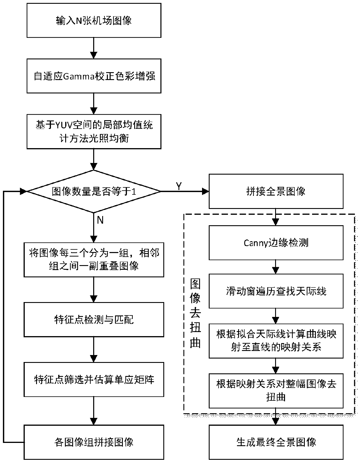
[0070] The invention discloses a panoramic image stitching method in an airport environment, such as figure 1 As shown, including the following steps:

[0071] S1: Color enhancement:

[0072] The sharpness of the image to be spliced ​​is one of the important factors affecting the accuracy of feature point detection. Through the color enhancement processing of adaptive Gamma correction on the stitched image, the image clarity can be improved, the color contrast of the image in the foggy day, rain and snow day and other under-lighted environments can be improved, and the accuracy of feature point detection can be effectively improved.

[0073] S2: Light balance:

[0074] The uneven illumination of the image to be spliced ​​will cause problems such as misdetection of feature information, fuzzy or loss of feature information, etc., which will have a greater impact on the accuracy of subsequent panoramic stitching and the rendering effect of panoramic images. By adopting the local mean st...


PUM


Abstract

The invention provides a panoramic image splicing method in an airport environment. The panoramic image splicing method comprises the following steps: firstly, preprocessing acquired images; adpotinga color difference correction method based on a YUV space to realize color consistency among multiple cameras; projecting a camera image to a cylindrical plane, and detecting feature points in the image by adopting a feature point detection algorithm for images after cylindrical projection; achieving rough matching of the feature point pairs in adjacent images; removing error feature point pairs through an RANSAC algorithm, calculating an accurate homography matrix between images to achieve uniform transition splicing between registered images through a gradual-in gradual-out fusion technology; carrying out canny edge detection on the panoramic image, selecting the longest line segment as the skyline position, and fitting a skyline smooth curve by using a least square method so that imagedistortion caused by splicing can be eliminated. A grouping iteration splicing method is adopted, error accumulation in the multi-path image splicing process is eliminated, and the splicing success rate and the splicing effect are improved.

Description

Technical field [0001] The invention belongs to the technical field of image processing, and particularly relates to a panoramic image stitching method in an airport environment. Background technique [0002] With the continuous development of the national civil aviation industry, the number of airports continues to increase. Traditional towers have many problems in airport scene monitoring, such as blind corners of the field of view, space occupation, personnel consumption, and insufficient resolution of traditional surveillance cameras. They can present the real scene of the airport scene in an integrated manner. Field of view and even panoramic images can solve these problems well. With the continuous development of technology in the image field, various fields have higher and higher requirements for image resolution. Special special imaging equipment is expensive, and due to the uniqueness of their respective environments and buildings, it is impossible to use a unified imag...

Claims


Application Information

Patent Timeline
IPC IPC(8): G06T3/40G06T5/00G06T3/00G06T7/13G06T7/181G06K9/46
CPCG06T3/4038G06T7/13G06T7/181G06V10/462G06T3/04G06T5/90Y02T10/40
Inventor 邱文嘉苗锋朱伟王寿峰白俊奇王扬红王成成朱恒刘羽颜世博
Owner NANJING LES ELECTRONICS EQUIP CO LTD
Why Eureka
Try Eureka