Novel pin insulator

A pin insulator, a new type of technology, applied in the field of new pin insulators, can solve the problems of low safety, cumbersome installation, and long stay time of installers, so as to simplify the connection operation, improve safety, and reduce the risk of being left alone The effect of probability

Inactive Publication Date: 2020-05-08
ZHEJIANG PINGKAI ELECTRIC POWER TECH CO LTD
View PDF8 Cites 3 Cited by
  • Summary
  • Abstract
  • Description
  • Claims
  • Application Information

AI Technical Summary

Problems solved by technology

[0004] However, the above-mentioned traditional pin insulators still have deficiencies. When installing pin insulators at high altitudes, it is necessary to use iron wires to wrap multiple turns at the corresponding positions of the high-voltage line...

Method used


Image

  • Novel pin insulator
  • Novel pin insulator
  • Novel pin insulator

Examples


Embodiment 1

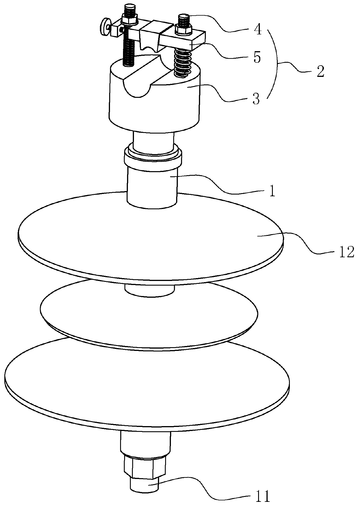
[0053] refer to figure 1 with figure 2 , is a new type of pin insulator disclosed in this embodiment, including an insulating pin body 1, the two ends of the insulating pin body 1 are respectively installed with a connecting part 11 and a mounting part 2, the connecting part 11 is used to connect with the utility pole, and the insulating pin Several umbrella covers 12 are fixed on the periphery of the body 1 .

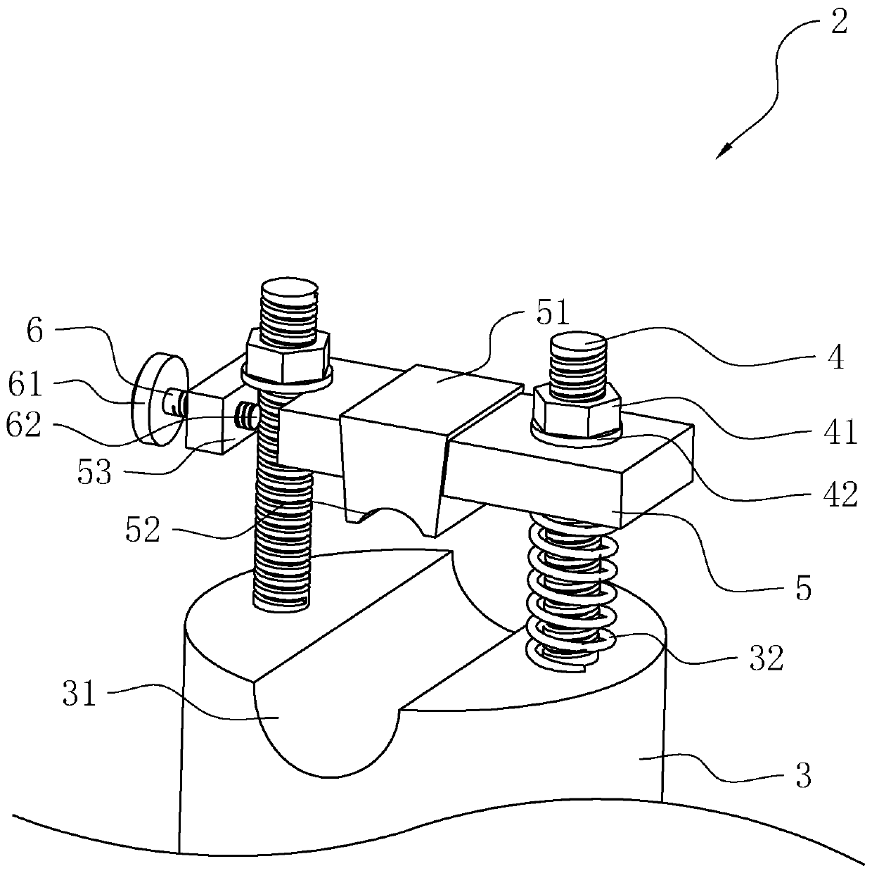
[0054] The mounting part 2 includes a mounting base 3, two threaded columns 4, and a clamping block 5. The side of the mounting base 3 away from the insulating needle body 1 is the upper surface of the mounting base 3, and the upper surface of the mounting base 3 is recessed with a mounting groove 31. , the mounting groove 31 is used to place the wires; two threaded columns 4 are arranged in parallel and fixed on the upper surface of the mounting seat 3, the mounting groove 31 is sandwiched between the two threaded columns 4; the clamping block 5 is connected to the ...

Embodiment 2

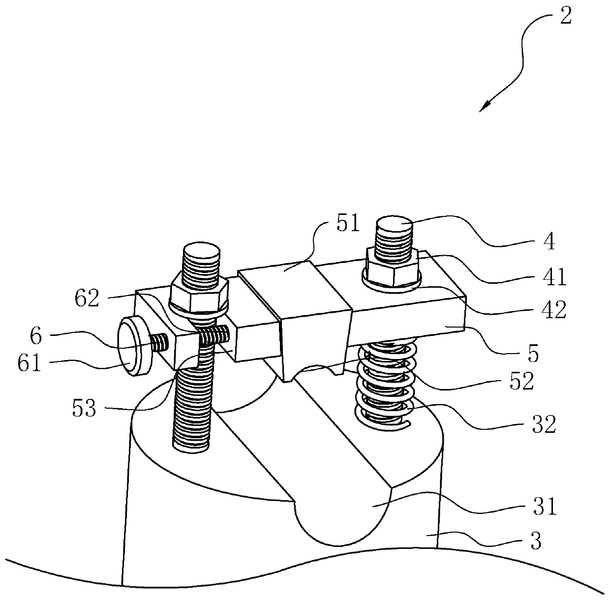
[0065] refer to image 3 , is a new type of pin insulator disclosed in this embodiment. The difference between this embodiment and Embodiment 1 is that the tail end 62 of the limiting member 6 penetrates into the groove wall of the clamping groove 53 to close the clamping groove. 53, and cooperate with the clamping groove 53 to form a closed ring-shaped restricted area.

[0066] The implementation principle of this embodiment is the same as that of Embodiment 1; where it is worth noting that, since the tail end 62 of the limiting member 6 penetrates into the groove wall of the clamping groove 53, the supporting point of the entire limiting member 6 There are two places. In the high-altitude and strong wind environment, the limiting member 6 is less likely to break, deform and other problems.

Embodiment 3

[0068] refer to Figure 4 , is a new type of pin insulator disclosed in this embodiment. The only difference between this embodiment and Embodiment 2 is that the limiting member 6 sequentially includes a large-diameter section 63, a transition section 64, and a small-diameter section 65 along its length direction. Portion 61 is located at the end of large-diameter section 63, and tail end 62 is located at the end of small-diameter section 65, and the external diameter of large-diameter section 63 is greater than the external diameter of small-diameter section 65, and the external diameter of transition section 64 is changed by large-diameter section 63 The direction to the small-diameter section 65 is gradually reduced; the threaded post 4 abuts against the bottom of the locking groove 53 , and the outer peripheral wall of the threaded post 4 abuts against the transition section 64 .

[0069] The implementation principle of this embodiment is: this embodiment is an improved so...


PUM


Abstract

The invention relates to a novel pin insulator, relates to the technical field of lightning protection insulators, and aims to solve a problem that a traditional pin insulator is inconvenient to install so that residence time of installation personnel at a high altitude is too long. The scheme comprises an insulating pin body. A connecting part and a mounting part are mounted at two ends of the insulating pin body; the mounting part comprises a mounting base, and a mounting groove is arranged in one side of the mounting base in a sunken mode; the mounting part further comprises two threaded columns fixed to one side of the mounting base and a clamping block located on one side of the mounting base, one end of the clamping block is rotatably connected to one threaded column, a clamping groove is arranged in the other end of the clamping block, and the other threaded column is clamped in the clamping groove; a limiting piece is mounted at a notch of the clamping groove; and a tight clamping block is fixed to the clamping block, and a locking piece used for pushing the tight clamping block to move towards the mounting groove is connected to each threaded column. According to the scheme, efficiency of mounting the pin insulator by mounting personnel can be improved, high-altitude mounting time of the mounting personnel is shortened, and safety is improved.

Description

technical field [0001] The invention relates to the technical field of lightning protection insulators, in particular to a novel pin insulator. Background technique [0002] Power needle insulators are widely used in power systems. Overhead transmission lines, busbars of power plants and substations, and external live conductors of various electrical equipment must be supported by insulators and connected to the earth (or ground) or Other conductors with potential difference are insulated. [0003] At present, the traditional pin insulators used in overhead power distribution lines, such as the Chinese patent with the authorized announcement number CN207282235U-a column type composite insulator for lightning protection lines, include glass fiber tubes, and porcelain tubes are arranged inside the glass fiber tubes. A series of resistance strips is arranged, and an arc-starting ring is arranged outside the glass fiber tube. The fixing screw is connected with the internal res...

Claims


Application Information

Patent Timeline
IPC IPC(8): H01B17/20H01B17/38
CPCH01B17/20H01B17/38
Inventor 夏德忠王敏超叶启周
Owner ZHEJIANG PINGKAI ELECTRIC POWER TECH CO LTD
Why Eureka
Try Eureka