Discharging device of plate bending machine

A technology of unloading device and plate rolling machine, which is applied to stripping devices, metal processing equipment, manufacturing tools, etc., can solve the problem of inability to adjust the size, and achieve the effect of reducing rigid contact and preventing deformation.

Inactive Publication Date: 2020-05-12
南京金球数控机床股份有限公司
View PDF0 Cites 1 Cited by
  • Summary
  • Abstract
  • Description
  • Claims
  • Application Information

AI Technical Summary

Problems solved by technology

[0003] The purpose of the present invention is to provide a plate bending machine unloading device to solve the problem that the size of the existing unloading device cannot be adjusted in the above background technology

Method used


Image

  • Discharging device of plate bending machine
  • Discharging device of plate bending machine
  • Discharging device of plate bending machine

Examples


Embodiment Construction

[0016] The following will clearly and completely describe the technical solutions in the embodiments of the present invention with reference to the accompanying drawings in the embodiments of the present invention. Obviously, the described embodiments are only some, not all, embodiments of the present invention. Based on the embodiments of the present invention, all other embodiments obtained by persons of ordinary skill in the art without making creative efforts belong to the protection scope of the present invention.

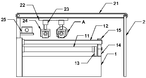
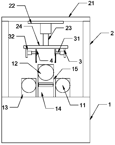
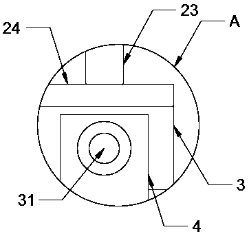
[0017] see Figure 1-3 , the present invention provides a technical solution: a plate rolling machine unloading device, including a plate rolling machine main body 1, the upper end of the plate rolling machine main body 1 is movably installed with a lower shaft roller 11 and an upper shaft roller 12 through a rotating shaft, and the upper The shaft roller 12 is movably installed on the upper end of the lower shaft roller 11, and one end of the lower shaft roll...


PUM


Abstract

The invention discloses a discharging device of a plate bending machine. The discharging device of the plate bending machine comprises a plate bending machine main body, a lower shaft roller and an upper shaft roller are movably arranged at the upper end of the plate bending machine main body through a rotating shaft, the upper shaft roller is movably arranged at the upper end of the lower shaft roller, a first support is movably arranged at one end of the lower shaft roller through the rotating shaft, a second support is fixedly arranged at one end of the upper shaft roller, a support seat ismovably arranged at the upper end of the second support through a hinge, and the support seat is movably connected with the upper shaft roller through a bearing. Mounting frames are fixedly mounted at the upper end of the plate bending machine main body, a conveyor belt is movably mounted between the mounting frames, and a motor is fixedly mounted at one end of one mounting frame through a mounting seat. According to the discharging device of the plate bending machine, the mounting frames and the conveyor belt are arranged at the upper end of the plate bending machine main body, first hydraulic cylinders, second hydraulic cylinders and clamping plates are fixedly arranged at the lower ends of the mounting frames through a mounting plate, the bent plate between the upper shaft roller and the lower shaft roller can be clamped, and then the plate is transmitted out through the conveyor belt.

Description

technical field [0001] The invention relates to the technical field of plate rolling machines, in particular to a plate rolling machine unloading device. Background technique [0002] The plate rolling machine is a kind of equipment that uses the work roll to bend the sheet material. It can form parts of different shapes such as cylindrical parts and conical parts. It is a very important processing equipment. Because the upper shaft roller and the lower shaft of the plate rolling machine The closed connection between the rollers makes it very troublesome when unloading. At the same time, because the size and diameter of the iron plates rolled out by the plate rolling machine are different, and the size of the unloading device of the existing plate rolling machine is fixed, so in When unloading, it is easy to cause the problem that the unloading device is too large to unload small-diameter plates or the unloading device is too small to unload large-diameter plates. Contents...

Claims


Application Information

Patent Timeline
Patent Type & Authority Applications(China)
IPC IPC(8): B21D45/06
CPCB21D45/06
Inventor 刘平
Owner 南京金球数控机床股份有限公司
Why Eureka
Try Eureka