A four-axis hydraulic locking device for a vertical machining center

A vertical machining center, hydraulic technology, applied in the direction of metal processing equipment, metal processing machinery parts, manufacturing tools, etc., can solve the problems of low production efficiency, high labor intensity, poor positioning accuracy of workpieces, etc., to improve production efficiency, The effect of reducing labor intensity

Active Publication Date: 2020-12-29
安徽合鑫机械设备制造有限公司
View PDF9 Cites 1 Cited by
  • Summary
  • Abstract
  • Description
  • Claims
  • Application Information

AI Technical Summary

Problems solved by technology

This method will produce positioning gaps, poor positioning accuracy of the workpiece, manual pre-positioning is required during operation, and the tooling only completes the fixed clamping work, the manual labor intensity is high, and the production efficiency is low. Some workpieces are also adsorbed and clamped by secondary pneumatics. , improve the clamping work, but the pneumatic clamping is prone to air leakage when the workpiece size is different, resulting in unstable clamping

Method used


Image

  • A four-axis hydraulic locking device for a vertical machining center
  • A four-axis hydraulic locking device for a vertical machining center
  • A four-axis hydraulic locking device for a vertical machining center

Examples


Embodiment 1

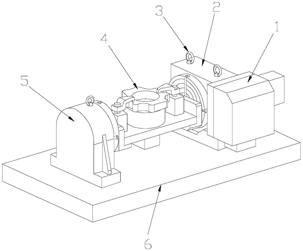
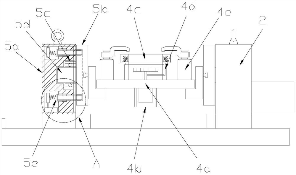
[0031] see Figure 1-Figure 4 , the present invention provides a four-axis hydraulic locking device for a vertical machining center. A four-axis hydraulic pressure 2 is provided on the right side of the top of the base 6. The base 6 and the four-axis hydraulic pressure 2 are welded by electric welding. 2 is electrically connected with the four-axis numerical control 1, and the left side of the top of the base 6 is provided with a four-axis tailstock 5, and the described base 6 is connected with the four-axis tailstock 5, and the four-axis tailstock 5 is connected to the four-axis The hydraulic shafts 2 are flexibly connected by the clamping device 4, and the four-axis tailstock 5 and the top of the four-axis hydraulics 2 are equipped with lifting rings 3;

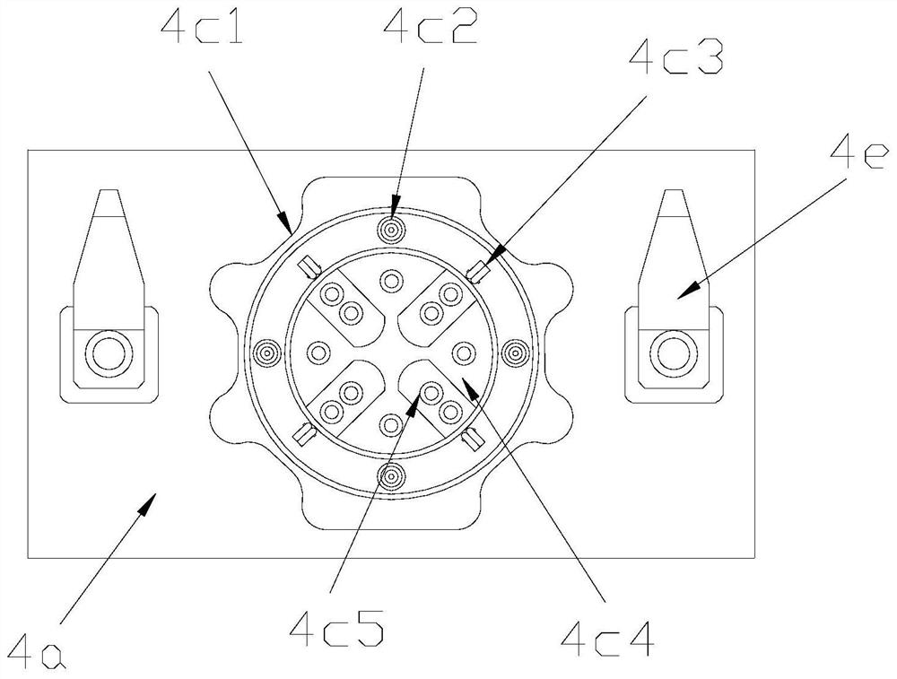
[0032] The clamping device 4 is composed of a workbench 4a, an air control valve 4b, a positioning sealing mechanism 4c, an air pipe 4d, and a corner cylinder 4e. An air control valve 4b is installed at the middle position...

Embodiment 2

[0038] see Figure 1-Figure 7 , the present invention provides a four-axis hydraulic locking device for a vertical machining center. The four-axis tailstock 5 is composed of a body 5a, a rotary chuck 5b, a bearing ring 5c, a rotating shaft 5d, and a locking mechanism 5e. A rotating shaft 5d is provided at the middle position of the rear end of the rotating chuck 5b, the rotating chuck 5b is fixedly connected to the rotating shaft 5d, the rotating shaft 5d is arranged inside the body 5a, and the rotating shaft 5d and the body 5a pass through the bearing ring 5c Clearance fit, the inside of the body 5a is equipped with a locking mechanism 5e up and down, and the locking mechanism 5e cooperates with the rotary chuck 5b.

[0039] The back surface of the rotary chuck 5b is provided with an inner gear ring groove 5b1.

[0040] The locking mechanism 5e is composed of an electromagnet 5e1, a second spring 5e2, an armature 5e3, a locking lever 5e4, and a first slide rail 5e5. The righ...


PUM


Abstract

The invention discloses a four-axis hydraulic locking device for a vertical machining center. The four-axis hydraulic locking device structurally comprises a four-axis numerical control device, a four-axis hydraulic device, lifting rings, a clamping device, a four-axis tailstock, and a base, wherein the clamping device comprises a worktable, a pneumatic control valve, a positioning seal mechanism,an air pipe and turning cylinders; the clamping device improves the pneumatic clamping of workpieces through the positioning seal mechanism; the condition that when the sizes of the workpieces are different, the leakage is caused, resulting in unstable clamping, influence on the positioning precision of the workpieces and scrapping of the workpieces is avoided; the four-axis tailstock is insertedinto an internal gear ring groove by a locking mechanism to enable a rotary chuck to control the worktable to be positioned for operation, so that the phenomenon the occurrence of positioning gaps results in low workpiece positioning precision is avoided; and through the design, the labor intensity is reduced, and the production efficiency is improved.

Description

technical field [0001] The invention relates to the field of hydraulic equipment, in particular to a four-axis hydraulic locking equipment for a vertical machining center. Background technique [0002] With the development of mechanical processing, the clamping workpiece needs to be convenient to use, precise clamping and positioning, time-saving, multi-purpose, versatile, safe and efficient, etc. Tooling in machining is one of the important components in the machinery industry. [0003] At present, most manufacturers will choose four-axis hydraulic fixtures, but traditional hydraulic fixtures generally use positioning pins directly when positioning workpieces. After manually determining the position of the workpiece, the positioning pins are extended from the fixture and inserted into the workpiece holes to fix the position of the workpiece. Effect. This method will produce positioning gaps, poor positioning accuracy of the workpiece, manual pre-positioning is required dur...

Claims


Application Information

Patent Timeline
Patent Type & Authority Patents(China)
IPC IPC(8): B23Q1/25B23Q3/08
CPCB23Q1/25B23Q3/08
Inventor 钱秀丽
Owner 安徽合鑫机械设备制造有限公司
Why Eureka
Try Eureka