Mechanical hand joint connection device

A technology of connecting device and manipulator, applied in manipulators, joints, manufacturing tools, etc., can solve the problems of large damper size, inconvenient joint detection, complex structure, etc.

Pending Publication Date: 2020-05-12
ZHENJIANG COLLEGE
View PDF0 Cites 2 Cited by
  • Summary
  • Abstract
  • Description
  • Claims
  • Application Information

AI Technical Summary

Problems solved by technology

[0003] In the prior art, the general damper is either large in size, does not meet the smaller size limit requirements of the movable joint connection, is not suitable for the application of controlling the movable joint connection of the main arm manipulator, or has a complex structure and high cost, and at the same time It is also inconvenient to install an angle sensor at the movable joint to detect the rotation angle of the joint

Method used


Image

  • Mechanical hand joint connection device
  • Mechanical hand joint connection device
  • Mechanical hand joint connection device

Examples


Embodiment 1

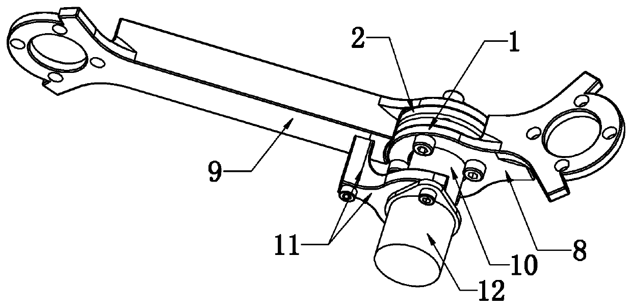
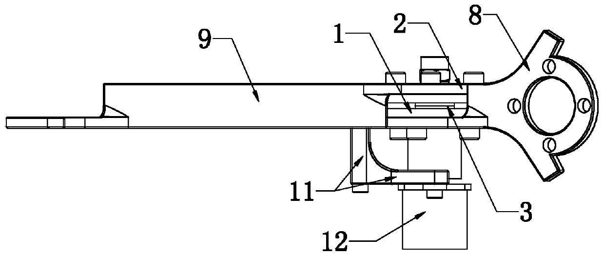
[0023] As shown in the figure, the manipulator joint connection device of the present invention includes a fixed disc 1 with a central flat hole, a rotating disc 2 with a central circular hole, an intermediate metal sheet 3 with a central flat hole, a flat pin shaft (with a flat screw pin shaft) 6 and the side metal sheet 5 that also has a central flat hole, the flat pin shaft 6 passes through the fixed disk 1, the middle metal sheet 3, the rotating disk 2, and the side metal sheet 5 in turn, and then the disc spring 4 is set and passed through the fastener (Self-locking nut) is locked and fixed, wherein the structure of the fixed plate 1 is as follows Image 6 As shown, there are four evenly distributed threaded connection holes, and the center has double-sided oblate holes (flat through holes). The rotating disk 2 also has the same four uniformly distributed connecting holes as the fixed disk 1. The difference is that the rotating disk 2 The center is a circular hole, and th...

Embodiment 2

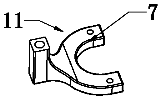
[0025] On the basis of Embodiment 1, further in order to meet the detection requirements, the middle part of the fixed plate 1 is fixedly connected with the connection block 10 by screwing. In order to make the structure compact, the bottom surface of the connection block 10 is provided with a bottom hole for accommodating the flat pin shaft 6 13. After the connecting block is fixedly installed on the fixed plate, the head of the flat pin shaft is limited in the bottom hole, and the second joint arm 9 is fixedly connected with the sensor bracket 11 by screws, and the top of the sensor bracket 11 is set in a C shape The connecting arm 7 and the angle sensor 12 are connected to the C-shaped connecting arm 7 by means of screws through the mounting flange. Simultaneously, because the sensor bracket 11 is screwed to the second articulated arm 9, the mounting flange of the angle sensor 12 is equivalent to the rotating disk 2. Fixed connection, the bottom end of the angle sensor 12 ha...


PUM


Abstract

The invention discloses a mechanical hand joint connection device. The mechanical hand joint connection device comprises a fixed disc with a central flat hole, a rotary disc with a central round hole,metal sheets with central flat holes, and a flat hinge pin; the flat hinge pin is sleeved with a disk spring after sequentially penetrating through the fixed disc, the middle metal sheet, the rotarydisc and the side metal sheet and then is locked and fixed through a fastener; a first joint arm is fixedly installed on the end surface of the outer side of the fixed disc through a fastener, and a second joint arm is fixedly installed on the end surface of the outer side of the rotary disc through a fastener; the rotary disc can generate frictional damping with the metal sheets in the rotating process, and the magnitude of the damping force can be adjusted by adjusting the pressing force of the disk spring. After the above structure is adopted, the mechanical hand joint connection device issimple in structure, damping is adjustable, through the skillful cooperative relationship, the safety and reliability are achieved, moreover, joints of a whole main arm mechanical hand can keep the accurate position posture, meanwhile, the rotation angle of the joints is conveniently detected through an angle sensor ingenious in design, and mechanical hand control is facilitated.

Description

technical field [0001] The invention relates to a connection device of a main arm manipulator joint with damping connection, in particular to a master-slave control main arm manipulator joint joint connection device, which belongs to the technical field of robots and manipulators. Background technique [0002] When performing master-slave control on multi-degree-of-freedom robots and manipulators, the control master arm manipulator is often designed according to the proportional scaling of the slave arm manipulator, so that the human arm can conveniently control the action or movement of the master arm manipulator to achieve slave control of the operation. The control of the main arm manipulator is generally not large in size, and it is necessary to ensure that the connection of each movable joint can keep the motion posture unchanged after the force is applied by the human hand. damping. [0003] In the prior art, the general damper is either large in size, does not meet t...

Claims


Application Information

Patent Timeline
Patent Type & Authority Applications(China)
IPC IPC(8): B25J17/00B25J17/02B25J19/02B25J19/00
CPCB25J17/00B25J17/02B25J19/00B25J19/0095B25J19/02
Inventor 赵飞吴琼兴百宪
Owner ZHENJIANG COLLEGE
Why Eureka
Try Eureka