
New energy automobile battery pack protection frame with shock absorption mechanism

A technology for new energy vehicles and battery packs, which is applied to battery pack components, isolation of batteries from their environment, circuits, etc., and can solve problems such as inconvenient placement and removal of battery packs, easy ash fall of battery packs, and impact on normal operation of battery packs. , to achieve the effect of good shockproof effect, simple structure and not easy to fall ash

Inactive Publication Date: 2020-05-12
柳州四通材料科技有限公司
View PDF0 Cites 0 Cited by
  • Summary
  • Abstract
  • Description
  • Claims
  • Application Information

AI Technical Summary

Problems solved by technology

[0002] The battery pack protection frame refers to a protection device to prevent the battery pack from being damaged due to the vibration of the external environment. There are certain disadvantages in the use of the battery pack protective frame. During the use of the battery pack protective frame, it is not convenient for people to place and take out the battery pack, and the battery pack is easy to fall into dust, which affects people's use. During the use of the battery pack, Its exterior is easily damaged by impact, which affects the normal operation of the battery pack. In addition, the shock-proof effect of the battery pack is ensured through the shock absorption of the battery pack protective frame, which brings certain advantages to the use of the battery pack protective frame. Therefore, we propose a new energy vehicle battery pack protection frame with a shock absorber

Method used


Image

  • New energy automobile battery pack protection frame with shock absorption mechanism
  • New energy automobile battery pack protection frame with shock absorption mechanism
  • New energy automobile battery pack protection frame with shock absorption mechanism

Examples


Embodiment Construction

[0017] In order to make the technical means, creative features, goals and effects achieved by the present invention easy to understand, the present invention will be further described below in conjunction with specific embodiments.

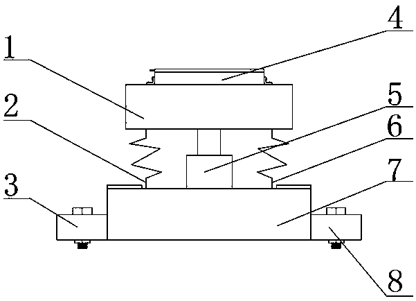
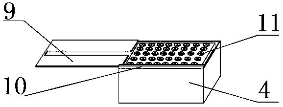
[0018] Such as Figure 1-4 As shown, the protective frame of the new energy vehicle battery pack with a shock absorbing mechanism includes a support base 7, the outer surface of the lower end of one side of the support base 7 is fixedly installed with the No. 1 fixing base 3, and the outer surface of the lower end of the other side of the support base 7 is fixed. No. 2 fixed seat 8 is installed, and the outer surface of the upper middle part of the support seat 7 is fixedly equipped with a fixed groove 5, and the outer surface of the upper end side of the support seat 7 is provided with a No. 1 damping spring 2, and the other side of the upper end of the support seat 7 The surface is provided with No. 2 shock-absorbing spring 6, and the inner surf...


PUM


Abstract

The invention discloses a new energy automobile battery pack protection frame with a shock absorption mechanism. The frame comprises a supporting seat, wherein a first fixed base is fixedly installedon the outer surface of the lower end of one side of the supporting seat, and a second fixed base is fixedly installed on the outer surface of the lower end of the other side of the supporting seat; afixed groove is fixedly formed in the outer surface of the middle of the upper end of the supporting seat, a first damping spring is arranged on the outer surface of one side of the upper end of thesupporting seat, and a second damping spring is arranged on the outer surface of the other side of the upper end of the supporting seat. According to the new energy automobile battery pack protectionframe with the shock absorption mechanism, the frame is provided with a battery pack placement box, a shock-proof battery pack frame, an elastic gasket, a placement groove, a supporting column and thefixed groove, people can conveniently open and close the battery pack placement box at any time, dust is prevented from falling into the battery pack placement box, it can be guaranteed that the battery pack is not impacted, the overall shock-proof effect of the battery pack protection frame can be improved, and better use prospects are brought.

Description

technical field [0001] The invention relates to the field of new energy vehicles, in particular to a protective frame for battery packs of new energy vehicles with a shock absorbing mechanism. Background technique [0002] The battery pack protection frame refers to a protection device to prevent the battery pack from being damaged due to the vibration of the external environment. There are certain disadvantages in the use of the battery pack protective frame. During the use of the battery pack protective frame, it is not convenient for people to place and take out the battery pack, and the battery pack is easy to fall into dust, which affects people's use. During the use of the battery pack, Its exterior is easily damaged by impact, which affects the normal operation of the battery pack. In addition, the shock-proof effect of the battery pack is ensured through the shock absorption of the battery pack protective frame, which brings certain advantages to the use of the batte...

Claims


Application Information

Patent Timeline
Patent Type & Authority Applications(China)
IPC IPC(8): H01M2/10B60K1/04F16F15/04
CPCB60K1/04F16F15/04H01M50/20H01M50/24Y02E60/10
Inventor 黄欣
Owner 柳州四通材料科技有限公司
Learn More