Pipe cable hoop and pipe cable laying assembly

A pipeline cable and cable technology, which is applied in the direction of cable laying equipment, etc., can solve the problems of affecting the service life of the cable, scratches on the outer wall of the cable, and cannot solve the sliding friction between the outer wall of the cable and the inner wall of the pipeline, so as to prevent damage and reduce traction resistance. Effect

Pending Publication Date: 2020-05-12
SHANGHAI ELECTRIC POWER DESIGN INST
View PDF0 Cites 2 Cited by
  • Summary
  • Abstract
  • Description
  • Claims
  • Application Information

AI Technical Summary

Problems solved by technology

[0003] However, even if the above-mentioned method of digging and setting a work well is used to pull the cable section by section, it still cannot solve the problem of sliding friction between the outer wall of the cable and the inner wall of the pipeline. This sliding friction will cause scratches on the outer wall of the cable and affect the service life of the cable.

Method used


Image

  • Pipe cable hoop and pipe cable laying assembly
  • Pipe cable hoop and pipe cable laying assembly
  • Pipe cable hoop and pipe cable laying assembly

Examples


Embodiment 1

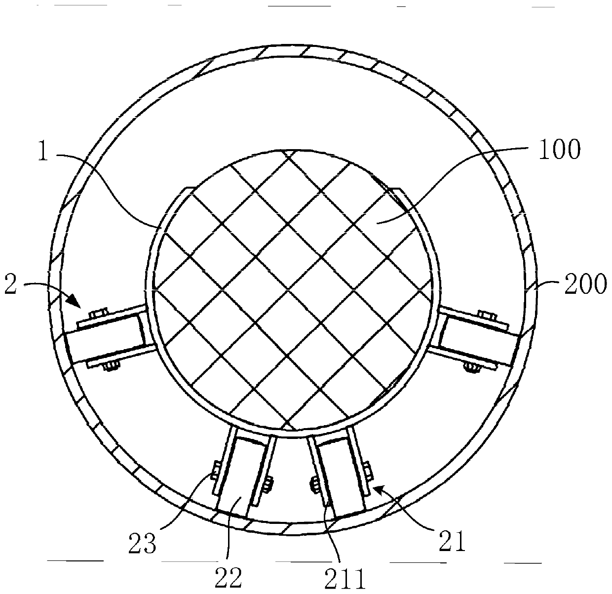
[0036] This embodiment provides a pipeline cable laying assembly, which can be applied in the field of cable laying, especially in the construction of pipeline cable laying. The pipeline cable laying assembly includes a plurality of pipeline cable hoops, and each pipeline cable hoop is arranged in parallel to be installed on the outer wall of the cable at intervals. When the cable is pulled by the traction machine and laid into the pipeline, each pipeline cable hoop can be used as a supporting structure between the outer wall of the cable and the inner wall of the pipeline, which can reduce the traction resistance of the traction machine and prevent the cable from rubbing against the inner wall of the pipeline. resulting in damage. Next, the pipe cable hoop will be described in detail.

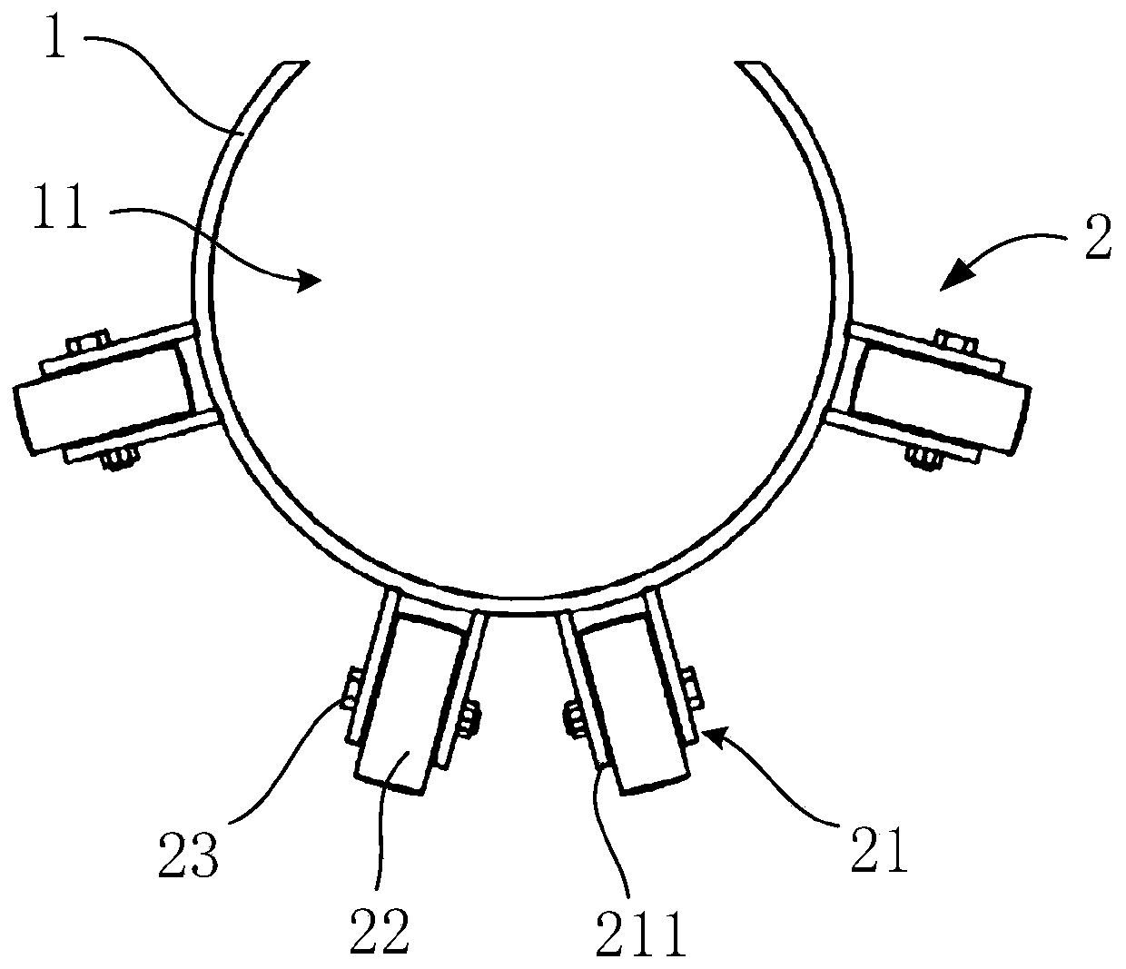
[0037] see figure 1 and combine figure 2 , the pipe cable hoop includes a hoop body 1 and at least two support bodies 2 . The ferrule 1 has a notch 11 capable of fitting and connecting wi...

Embodiment 2

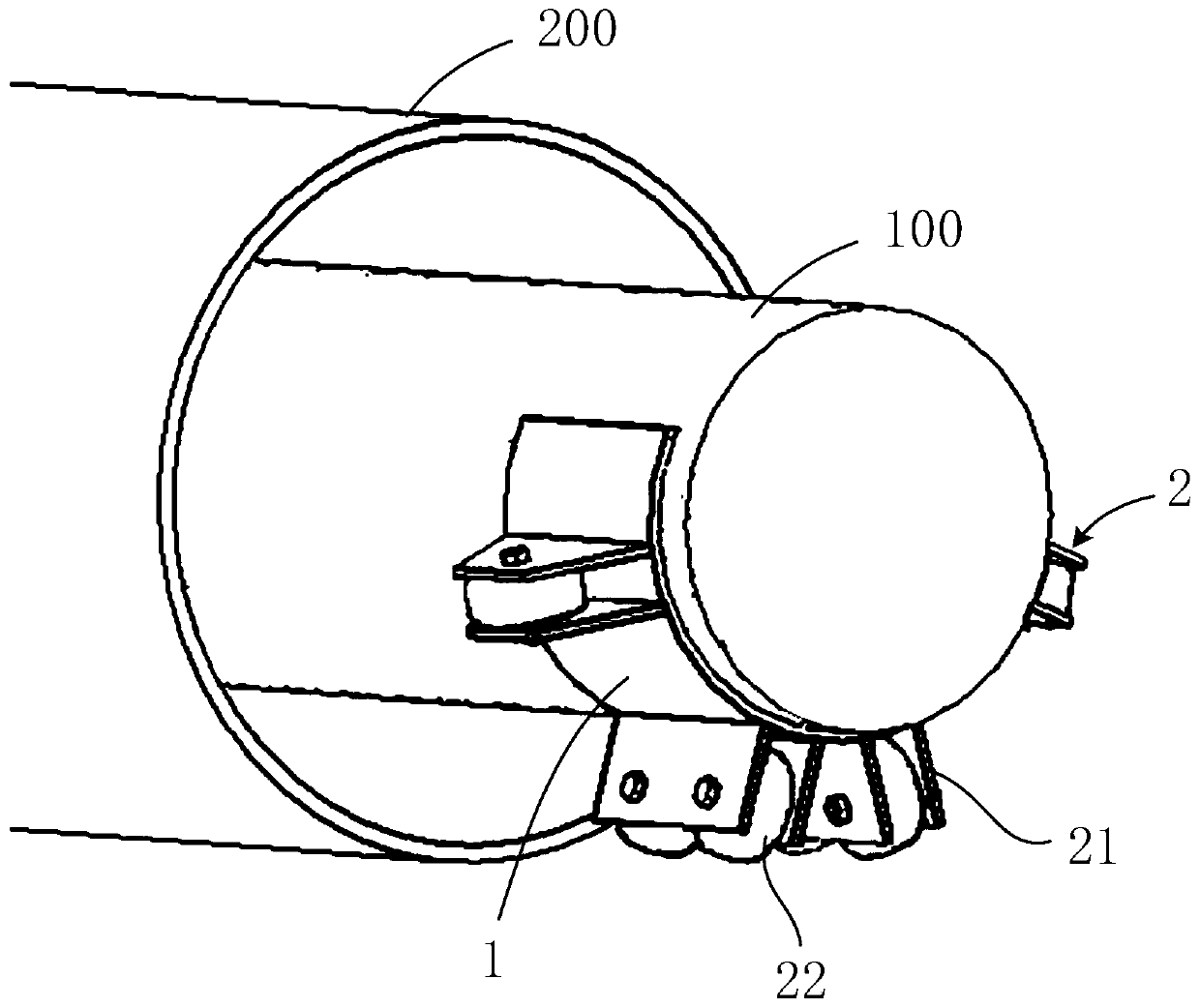
[0054] see Figure 5 The difference between the pipe cable hoop provided in this embodiment and the pipe cable hoop in the previous embodiment is that the support body 2 is only symmetrically arranged on both sides near the bottom of the hoop body 1, or one of the support bodies 2 Located at the bottom of the hoop body 1, it is symmetrically arranged on both sides of the support body 2 to form an inferior arc-shaped arc-shaped support portion. That is, the pipe cable hoop provided in this embodiment can be suitable for laying the cable 100 in a straight pipe 200, and reduce the number of supports 2 arranged on both sides of the hoop body 1, saving cost and lightening the pipe cable. The weight of the hoop.


PUM


Abstract

The invention belongs to the technical field of cable laying, and discloses a pipe cable hoop and a pipe cable laying assembly. The pipe cable hoop comprises a hoop body and at least two supporting bodies, and the hoop body is provided with a notch part which can be adaptively connected with the outer wall of a cable; each supporting body comprises a supporting frame and idler wheels, wherein thesupporting frame is fixedly connected with the hoop body and extends towards the outer side of the hoop body, the idler wheels are arranged at the end, away from the hoop body, of the supporting frame, and the idler wheels are distributed in an arc shape to form an arc-shaped supporting part capable of abutting against the inner wall of a pipe for laying cables. The pipe cable hoop provided by theinvention can be connected to the outer wall of a to-be-laid cable through the notch part of the pipe cable hoop; when the cable is subjected to traction force to be arranged in the pipe in a penetrating mode, the idler wheels are connected with the inner wall of the pipe in a rolling mode, the hoop body is supported in the pipe, the cable borne by the hoop body is separated from the pipe, the cable can be prevented from making contact with the inner wall of the pipeline in the cable laying operation, the traction resistance is reduced, and the outer wall of the cable is prevented from beingdamaged.

Description

technical field [0001] The invention relates to the technical field of cable laying, in particular to a pipeline cable hoop and a pipeline cable laying assembly. Background technique [0002] The pipeline laying construction of the cable generally relies on the traction machinery located outside the end of the pipeline to pull the cable so that the cable penetrates into the pipeline. During the laying process, the outer wall of the cable is in direct contact with the inner wall of the pipe and forms sliding friction. The magnitude of the sliding friction is proportional to the weight of the cable, that is, it is proportional to the length of the contact part between the cable and the inner wall of the pipe, and the tensile capacity of the cable itself Therefore, in order to ensure that the cable is not broken, it is necessary to dig a work well between the cable ducts to pull the cable section by section. [0003] However, even if the cable is pulled section by section in t...

Claims


Application Information

Patent Timeline
Patent Type & Authority Applications(China)
IPC IPC(8): H02G1/08
CPCH02G1/08
Inventor 何仲
Owner SHANGHAI ELECTRIC POWER DESIGN INST
Why Eureka
Try Eureka