
Gas detection system based on open type photoacoustic resonant cavity

A gas detection system and acoustic resonance technology, applied in measuring devices, material analysis through optical means, instruments, etc., can solve the problems of cumbersome filling and purification steps, inconvenient practical operation, high cost, etc., and achieve long-term high-precision online Effects of detection, improvement of sensitivity and accuracy, reduction of instrument cost and difficulty of operation

Active Publication Date: 2020-05-15
XIDIAN UNIV
View PDF1 Cites 5 Cited by
  • Summary
  • Abstract
  • Description
  • Claims
  • Application Information

AI Technical Summary

Problems solved by technology

[0004] However, the existing photoacoustic detection device uses the optical window of the closed photoacoustic cell, which will interact with the laser light source and generate large background noise, which greatly limits the sensitivity and accuracy of the detectio

Method used


Image

  • Gas detection system based on open type photoacoustic resonant cavity
  • Gas detection system based on open type photoacoustic resonant cavity
  • Gas detection system based on open type photoacoustic resonant cavity

Examples


Embodiment 1

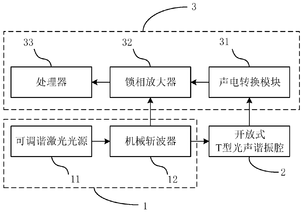
[0037] See figure 1 , figure 1 It is a schematic structural diagram of a gas detection system based on an open photoacoustic resonator provided by an embodiment of the present invention, including:

[0038] A light source module 1, configured to generate incident light;

[0039] The open photoacoustic resonator 2 is connected to the light source module 1, and has a ventilation window to allow the gas to be measured to enter the cavity; The gas to be measured is irradiated to generate a photoacoustic signal;

[0040] The signal processing module 3 is connected to the open photoacoustic resonant cavity 2, and is used for converting the photoacoustic signal into an electrical signal and processing the electrical signal to complete the detection of the gas to be measured.

[0041] Further, see figure 2 , figure 2 It is a schematic structural diagram of another gas detection system based on an open photoacoustic resonator provided by an embodiment of the present invention; w...

Embodiment 2

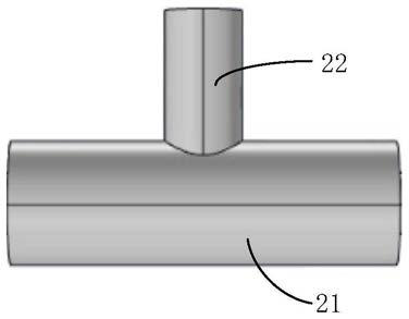
[0062] On the basis of the first embodiment above, the present invention also provides a gas detection system based on an open photoacoustic resonator, wherein the open photoacoustic resonator 2 also includes The buffer cavity 23 is used to reduce the impact of noise caused by surrounding gas disturbance.

[0063] Further, the buffer cavity 23 is a cylindrical structure, and the diameter of the buffer cavity 23 is larger or smaller than the diameter of the absorption cavity 21 . See Figure 4a~4b , Figure 4a~4b is a schematic structural view of an open photoacoustic resonator with a buffer cavity provided by an embodiment of the present invention, wherein, Figure 4a The diameter of the buffer chamber 23 is greater than the diameter of the absorption chamber 21, Figure 4b The diameter of the buffer chamber 23 is smaller than the diameter of the absorption chamber 21.

[0064] Specifically, the greater the difference between the diameter of the buffer chamber 23 and the d...


PUM


Abstract

The invention discloses a gas detection system based on an open-type photoacoustic resonant cavity, and the system comprises: a light source module which is used for generating incident light; an opentype photoacoustic resonant cavity that is connected with the light source module and is provided with a ventilation window so as to enable gas to be detected to enter the cavity, and the open type photoacoustic resonant cavity is used for irradiating the gas to be detected in the cavity according to the incident light so as to generate a photoacoustic signal; and a signal processing module thatis connected with the open type photoacoustic resonant cavity and is used for converting the photoacoustic signal into an electric signal and processing the electric signal so as to finish the detection of the gas to be detected. According to the gas detection system based on the open type photoacoustic resonant cavity, the open type resonant photoacoustic cell is used, an optical lens does not need to serve as a window, the problem that background noise is generated due to the interaction of an optical window and a laser light source in an existing closed type photoacoustic cell is solved, and the sensitivity and accuracy of gas detection are improved.

Description

technical field [0001] The invention belongs to the technical field of optical detection of trace gas, and in particular relates to a gas detection system based on an open photoacoustic resonant cavity. Background technique [0002] Trace gases are particles whose concentration in the atmosphere is lower than 10, and they participate in biogeochemical cycles under various physical, chemical, and biological effects. Some trace pollutants in the atmosphere have low levels but can have a huge impact on the environment. Nondestructive on-line detection of trace gases has important research value and application significance in the fields of atmospheric monitoring, industrial safety, medical diagnosis and so on. as SO in the atmosphere 2 cause acid rain, CO 2 、CH 4 Is the culprit of the greenhouse effect. However, the insulation system of the transformer will age during long-term work, resulting in C 2 h 4 , CO and other trace gases, through the detection of these trace ga...

Claims


Application Information

Patent Timeline
IPC IPC(8): G01N21/17G01N21/03
CPCG01N21/1702G01N21/0303G01N2021/1704
Inventor 刘丽娴邵晓鹏章学仕宦惠庭张乐马生存程坤
Owner XIDIAN UNIV
Learn More