
Zoom lens, camera module and electronic device

A zoom lens and component technology, which is applied to the focusing device, focusing device, focusing device and other directions of a camera, can solve the problems of high precision requirements, difficulty in focusing movement accuracy of the zoom lens, and small moving range of the zoom lens, etc. The effect of moving precision

Active Publication Date: 2020-05-15
GUANGDONG OPPO MOBILE TELECOMM CORP LTD
View PDF26 Cites 12 Cited by
  • Summary
  • Abstract
  • Description
  • Claims
  • Application Information

AI Technical Summary

Problems solved by technology

[0002] In the related technology, the zoom lens can realize the change of the overall focal length through the movement of the lens group. However, most of the current driver chips are only suitable for realizing the focusing and optical anti-shake of the fixed-focus lens. When realizing optical image stabilization, the overall movement range of the zoom lens is also small, and the effective control bit of the driver chip can control the movement of the lens group with high precision even if it is small
However, in the zoom lens, the movement range of the lens group during the zooming process is relatively large, and the accuracy requirements for focusing after zooming are relatively high. In the case of fewer effective control bits of the driver chip, it is difficult to achieve zooming at the same time. Guaranteed movement accuracy of the focus of the zoom lens

Method used


Image

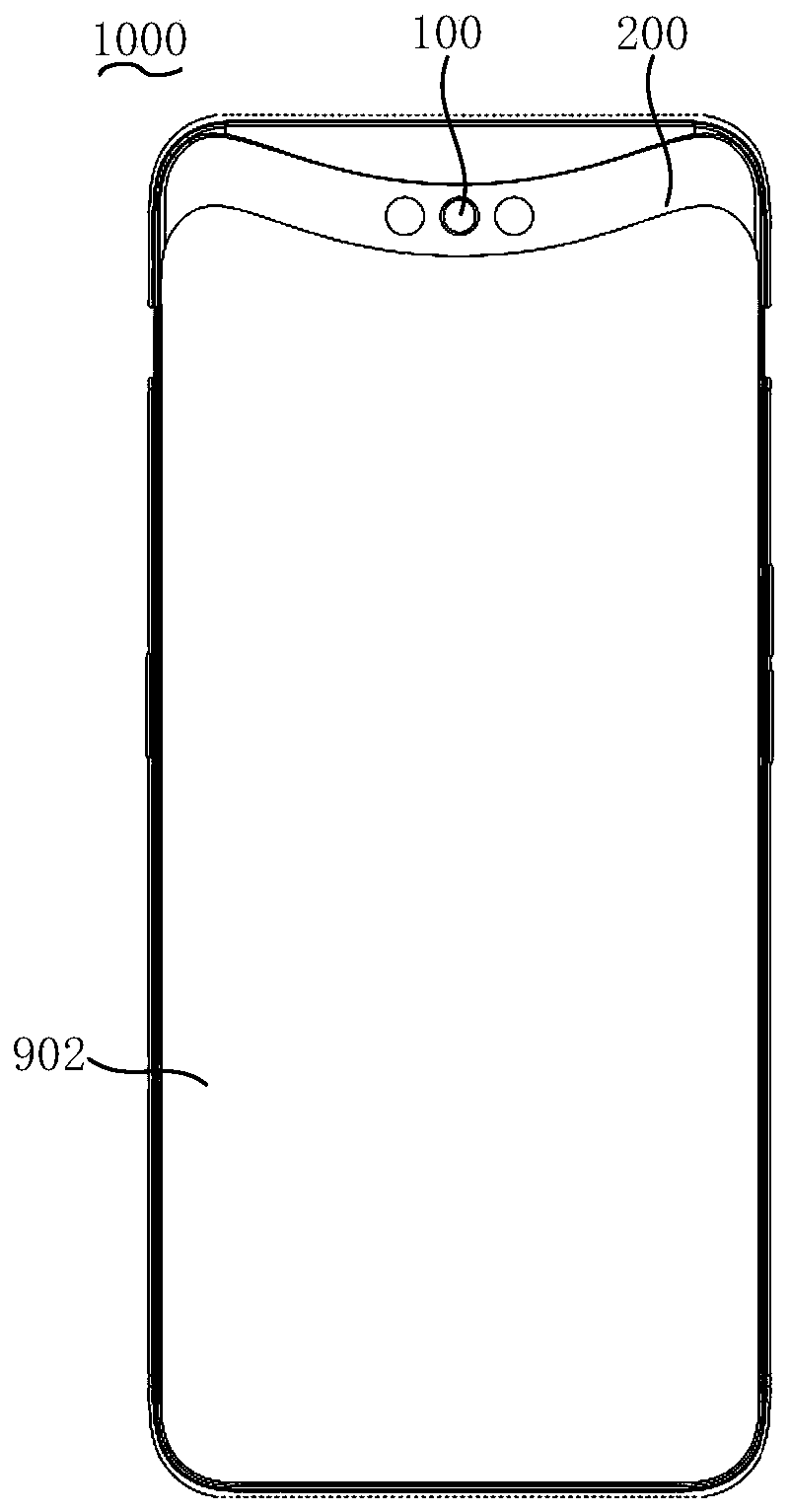
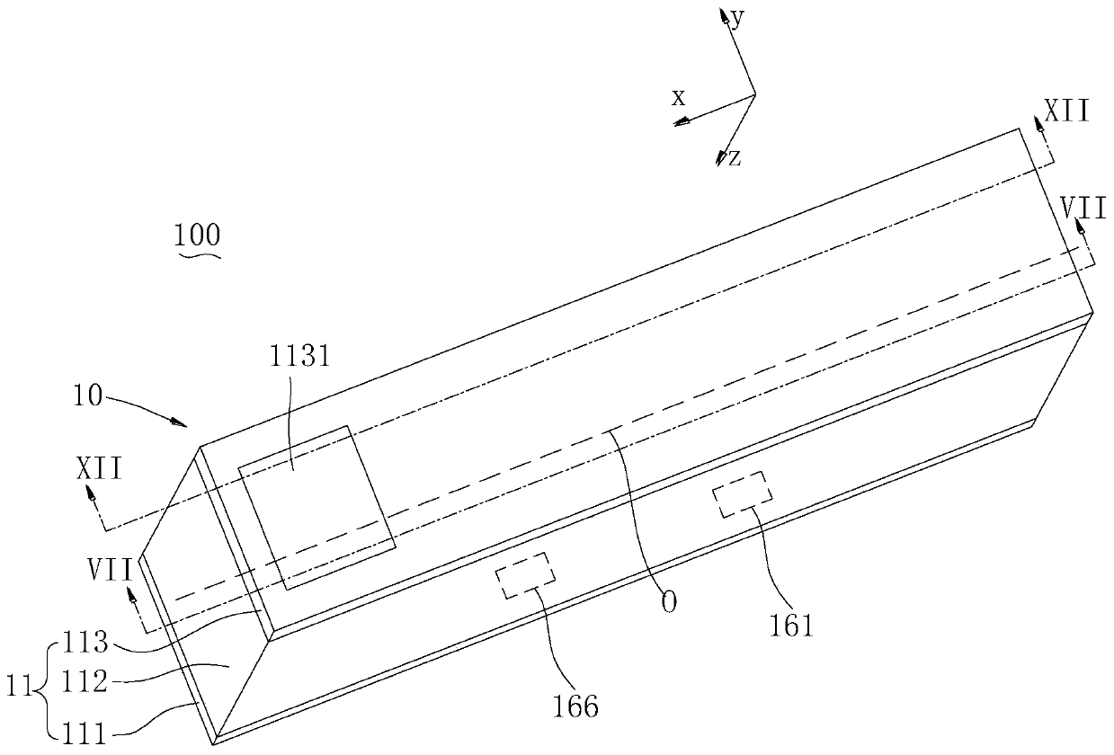
  • Zoom lens, camera module and electronic device
  • Zoom lens, camera module and electronic device
  • Zoom lens, camera module and electronic device

Examples


Embodiment Construction

[0022] Embodiments of the present application will be further described below in conjunction with the accompanying drawings. The same or similar reference numerals in the drawings represent the same or similar elements or elements having the same or similar functions throughout.

[0023] In addition, the embodiments of the present application described below in conjunction with the accompanying drawings are exemplary, and are only used to explain the embodiments of the present application, and should not be construed as limitations on the present application.

[0024] In the present application, unless otherwise clearly specified and limited, a first feature being "on" or "under" a second feature may mean that the first and second features are in direct contact, or that the first and second features are indirect through an intermediary. touch. Moreover, "above", "above" and "above" the first feature on the second feature may mean that the first feature is directly above or ob...


PUM


Abstract

The invention discloses a zoom lens, a camera module and an electronic device. The zoom lens comprises a shell, a first lens assembly, a second lens assembly, a third lens assembly and a first drivingchip. The first driving chip comprises a first control end, a second control end, a third control end and a fourth control end, and the first control end and the second control end respectively control the second lens assembly and the third lens assembly to move relative to the first lens assembly so as to realize zooming of the zoom lens; the third control end is used for controlling the third lens assembly to move relative to the first lens assembly under the first target focal length so as to realize focusing of the zoom lens; and the fourth control end is used for controlling the third lens assembly to move relative to the first lens assembly under the second target focal length so as to realize focusing of the zoom lens, and the first target focal length is different from the secondtarget focal length. According to the invention, under the condition that the effective control bits of the driving chip are few, focusing control is achieved through the independent control end of the zoom lens, and the focusing moving precision is guaranteed.

Description

technical field [0001] The present application relates to the technical field of consumer electronics, in particular to a zoom lens, a camera module and an electronic device. Background technique [0002] In the related technology, the zoom lens can realize the change of the overall focal length through the movement of the lens group. However, most of the current driver chips are only suitable for realizing the focusing and optical anti-shake of the fixed-focus lens. When implementing optical image stabilization, the overall movement range of the zoom lens is also small, and the effective control bit of the driver chip can control the movement of the lens group with high precision even if it is small. However, in the zoom lens, the movement range of the lens group during the zooming process is relatively large, and the accuracy requirements for focusing after zooming are relatively high. In the case of fewer effective control bits of the driver chip, it is difficult to achie...

Claims


Application Information

Patent Timeline
Patent Type & Authority Applications(China)
IPC IPC(8): G02B7/04G03B13/34G03B30/00
CPCG03B13/34G02B7/10G03B30/00G02B7/021G02B7/04G02B7/08G02B7/1805G02B13/0065G02B27/646G02B13/009G03B17/17G03B3/10G03B5/00G03B2205/0007G03B2205/0046G02B7/102G02B15/14G03B13/36G03B2205/003G03B2205/0069
Inventor 徐青
Owner GUANGDONG OPPO MOBILE TELECOMM CORP LTD
Learn More