Take-up control box
A control box and box body technology, which is applied to devices with bendable leads, electrical components, bases/housings, etc., can solve the problem that the control box on the cable cannot automatically take up the wires, etc., so as to avoid malfunction, compact layout, and ensure The effect of sealing performance
- Summary
- Abstract
- Description
- Claims
- Application Information
AI Technical Summary
Problems solved by technology
Method used
Image
Examples
specific Embodiment 1
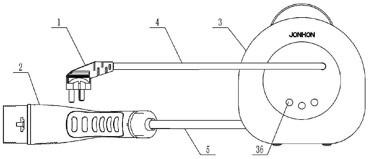
[0056] Such as figure 1 As shown, the take-up control box is used in the mode 2 charging device. According to the national standard GB / T1847.1-2015, the charging gun is divided into four categories, including the mode 2 charging gun. The mode 2 charging gun is a portable charging gun, which can be used for For home charging, the mode 2 charging device here refers to the charging device using the mode 2 charging gun.
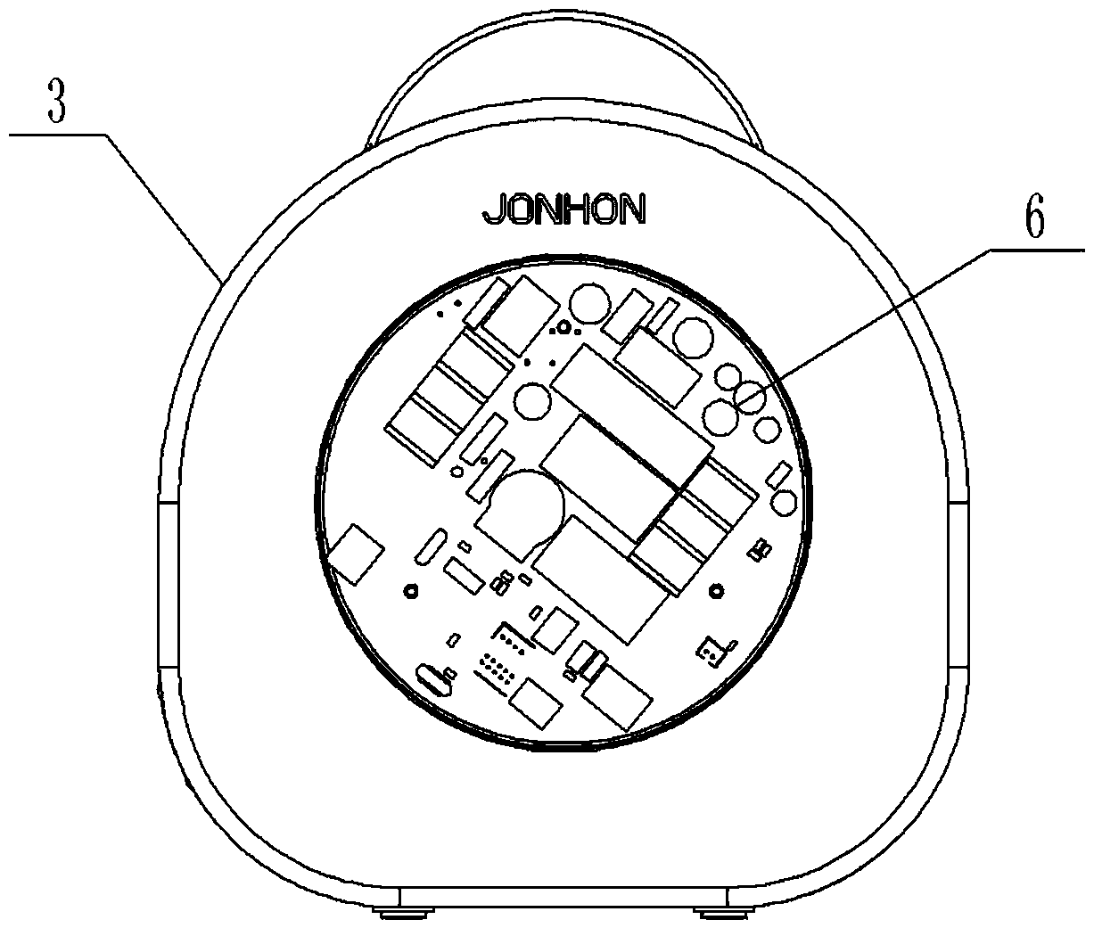
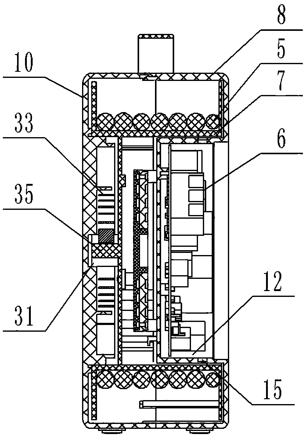
[0057] Such as figure 2 and image 3 As shown, the take-up control box 3 includes a box body and a circuit board 6 fixed in the box body, and also includes a turntable 7 rotatably assembled in the box body, and the turntable 7 is used to wind the cable 5 for passing the cable 5 and The charging gun 2 is conductively connected, and the retractable operation of the cable 5 can be realized through the circumferential rotation of the turntable 7 .
[0058] Specifically, the box body includes a box body, and the box body includes a front shell 8 and a rear shell 1...
specific Embodiment 2
[0085] It differs from Example 1 in that:
[0086] There are no ratchet segments and pawls in the locking mechanism. The locking mechanism includes a compression block arranged on the box body. When the cable is unwound to the required length, the compression block is pushed, and under the action of the compression block , the cable can be locked and pressed on the turntable, and the pressing block can be pushed in the opposite direction to unlock the cable. Under the driving action of the take-up elastic member, the automatic take-up of the take-up control box can be realized. In this embodiment, the take-up and release operation of the take-up control box can be completed by one person, that is, the operator operates at the position of the take-up control box. Locking; the take-up and release operation of the take-up control box in this embodiment can also be completed by two people.
specific Embodiment 3
[0088] It differs from Example 1 in that:
[0089]There is no groove structure on the front shell, and an opening is set at the bottom of the barrel of the front shell. A radial flange is set on the radial flange, bolt holes are set on the radial flange to form a flange plate, and the box body insulator is fixed on the radial flange with fastening bolts. At this time, the box body insulator needs to be sealed and assembled on the corresponding On the radial flange, the sealing arrangement of the circuit board accommodating cavity is realized.
[0090] In the above separation method, the circuit board accommodation cavity is surrounded by the box body and the box body insulator, and the box body insulator forms part of the cavity wall of the transition structure accommodation cavity, and the conductive ring piece, that is, the circuit board transfer terminal is located in the circuit board accommodation cavity , the inner wire drawn from the circuit board can be directly conne...
PUM
 Abstract
Description
Claims
Application Information
 - R&D
- Intellectual Property
- Life Sciences
- Materials
- Tech Scout
- Unparalleled Data Quality
- Higher Quality Content
- 60% Fewer Hallucinations
Browse by: Latest US Patents, China's latest patents, Technical Efficacy Thesaurus, Application Domain, Technology Topic, Popular Technical Reports.
© 2025 PatSnap. All rights reserved.Legal|Privacy policy|Modern Slavery Act Transparency Statement|Sitemap|About US| Contact US: help@patsnap.com


