Suspension insulator rotary plug pin device

A suspension insulator and insulator technology, applied in switchgear, electrical components, overhead line/cable equipment, etc., can solve the problems of long working hours, unbalanced stress of insulators, and increase the danger of high-altitude workers, and achieve simple operation, High degree of automation and the effect of reducing the risk of manual work

Active Publication Date: 2021-01-01
ANHUI UNIVERSITY OF TECHNOLOGY
View PDF12 Cites 0 Cited by
  • Summary
  • Abstract
  • Description
  • Claims
  • Application Information

AI Technical Summary

Problems solved by technology

[0002] The amount of suspension insulator strings in the substation is huge, and the suspension insulator strings are in the open environment for a long time. Under the influence of environmental factors such as wind, sun and sun, the internal stress of the insulators will be unbalanced, resulting in low zero value of the insulators and even structural damage. As a result, the damage defects of the suspension insulator strings in the substation are increasing day by day
[0003] At present, there is no special replacement tool suitable for the suspension insulator strings in the station. When replacing the suspension insulator strings in the station, it can only be replaced by the traditional method, that is, the hand hoist is used to pull the wires and clamps, so that the suspension insulator strings are in the In the non-stressed state, the damaged insulators are disassembled and new insulators are installed. This method requires the cooperation of high-altitude operations and ground operations. Generally, three people are required to cooperate at high altitudes, and two people are required to connect on the ground. Take tools and insulators. This operation method takes a long time and increases the danger of workers working at heights. Moreover, the traction force of the lever hoist is not easy to control, and it is easy to generate overload traction, which will cause damage to the wires or clamps and affect the quality of work.

Method used


Image

  • Suspension insulator rotary plug pin device
  • Suspension insulator rotary plug pin device
  • Suspension insulator rotary plug pin device

Examples


Embodiment 1

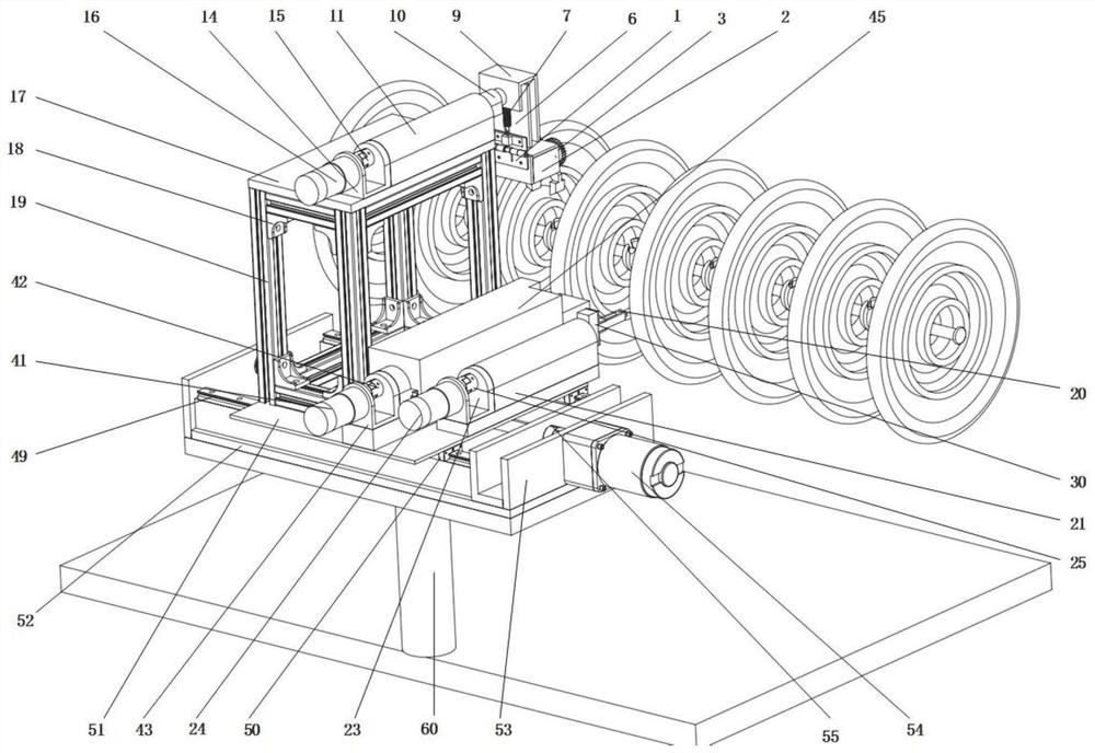
[0030] Such as figure 1 as shown, figure 1It is a structural diagram of the suspended insulator rotary plugging device; the suspended insulator rotary plugging device in the present invention includes an insulator straightening device, an insulator pin pulling device, an insulator plugging device, a lateral moving device and a total fixed base 60 . The lateral moving device is fixedly arranged on the general fixed base 60, and the insulator straightening device, insulator pin pulling device and insulator plugging device are all fixedly arranged on the surface of the lateral transfer flange 51 of the lateral moving device.

[0031] Specifically, the insulator straightening device clamps the insulator sheet through the gear jaw 3, and drives the gear jaw 3 to extend or retract through the servo motor. The gear jaw 3 and the clamping fixed plate 9 The spring hinge 1 and the clamping linear guide rail 8 are used to connect between them, so as to meet the freedom and attitude req...

Embodiment 2

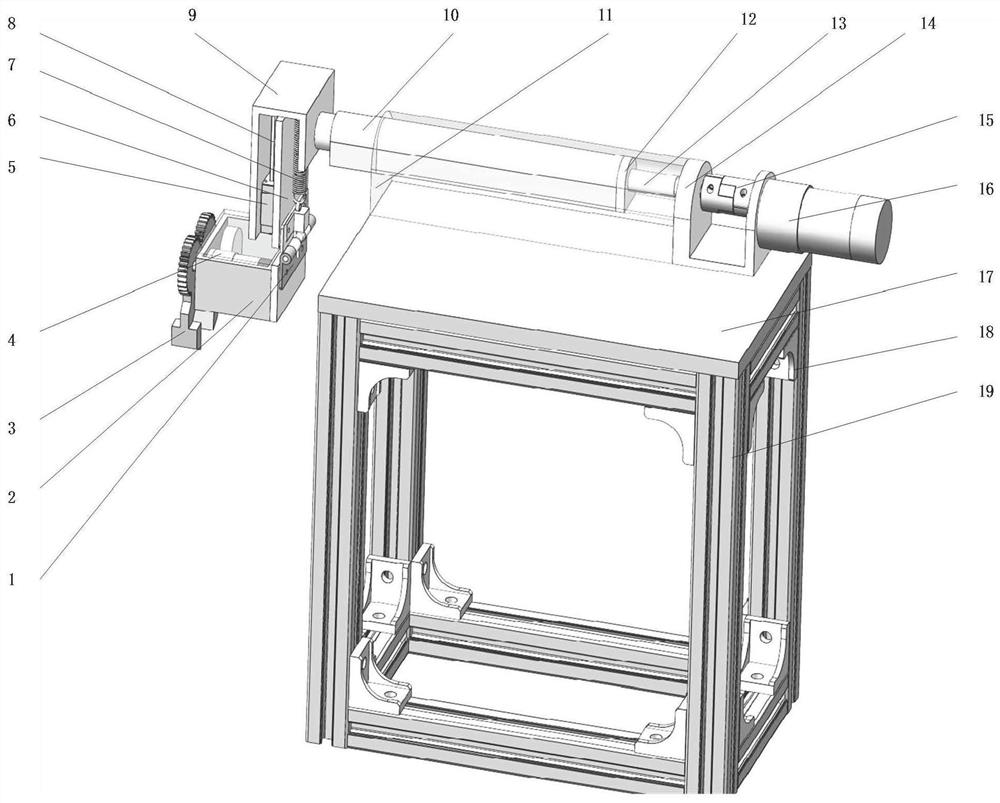
[0035] Such as figure 2 as shown, figure 2 It is a structural schematic diagram of the insulator straightening device; the insulator straightening device includes a profile frame, a straightening telescopic component and a straightening clamping component. The straightening clamping assembly is used to clamp the insulator sheet; the straightening telescopic assembly is used to drive the straightening clamping assembly to clamp the insulator sheet to rotate.

[0036] The straightening telescopic assembly includes a straightening fixed base plate 17, a clamping fixed plate 9, a straightening U-shaped linear guide rail slider 10, a straightening U-shaped linear guide rail 11, a straightening screw nut 12, a straightening screw 13, Set the telescopic servo motor adapter flange 14, set the telescopic servo motor coupling 15, and set the telescopic servo motor 16. The straightening fixed base plate 17 is fixedly connected, and is connected with the straightening screw 13 through...

Embodiment 3

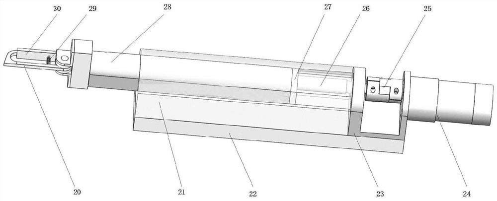
[0042] Such as image 3 as shown, image 3 It is a structural schematic diagram of the insulator pin pulling device. The insulator pin pulling device includes a pin pulling telescopic assembly and a pin removing hook; the pin removing hook is used to hook the iron pin in the iron cap of the insulator, and the insulator pin pulling telescopic assembly is used to extend or retract the pin removing hook .

[0043] Specifically, the insulator pin-pull telescopic assembly includes a pin-pull U-shaped linear guide rail 21, a pin-pull fixed base plate 22, a pin-pull telescopic servo motor adapter flange 23, a pin-pull telescopic servo motor 24, and a pin-pull telescopic servo motor coupling Device 25, pin-pull leading screw 26, pin-pull leading screw nut 27, pin-pull U-shaped linear guide rail slide block 28.

[0044] The pin-pull telescopic servo motor 24 is fixedly connected to the pin-pull fixed base plate 22 through the pin-pull telescopic servo motor adapter flange 23, and is...


PUM


Abstract

The invention discloses a suspension insulator rotary pin plugging and unplugging device. The device comprises: an insulator correcting device for correcting an insulator sheet; an insulator pin pulling device used for pulling an iron pin in an insulator sheet iron cap; an insulator bolt device used for inserting the iron pin into an insulator iron cap; a transverse moving device used for adjusting the positions of the insulator pin pulling device, the insulator bolt device and the insulator correcting device; and a transverse moving device fixedly arranged on the main fixing base, wherein theinsulator correcting device, the insulator pin pulling device and the insulator bolt device are all fixedly arranged on the transverse moving device. An insulator unloading device, an insulator replacing device and an insulator supporting device are all driven by a driving device, so that the driving device drives a lead screw to rotate and drives all the devices to move front and back to meet the requirement for the freedom degree of all the devices, the insulator replacing operation is achieved, the automation degree is high, operation is easy, and the risk of manual operation is reduced.

Description

technical field [0001] The invention relates to the technical field of electric facility maintenance, in particular to a rotary plugging and pulling out pin device for a suspension insulator. Background technique [0002] The amount of suspension insulator strings in the substation is huge, and the suspension insulator strings are in the open environment for a long time. Under the influence of environmental factors such as wind, sun and sun, the internal stress of the insulators will be unbalanced, resulting in low zero value of the insulators and even structural damage. As a result, the damage defects of suspension insulator strings in substations are increasing day by day. [0003] At present, there is no special replacement tool suitable for the suspension insulator strings in the station. When replacing the suspension insulator strings in the station, it can only be replaced by the traditional method, that is, the hand hoist is used to pull the wires and clamps, so that ...

Claims


Application Information

Patent Timeline
Patent Type & Authority Patents(China)
IPC IPC(8): H02G1/02H02B3/00
CPCH02B3/00H02G1/02
Inventor 高文斌黄琪王鹏
Owner ANHUI UNIVERSITY OF TECHNOLOGY
Why Eureka
Try Eureka