Expansion wedge unit

A wedge-shaped, guiding unit technology, applied in the direction of gear transmission mechanism, drum brake, brake type, etc., can solve the problems of shaking contact surface, wear, braking application can not be properly controlled, etc., to achieve the effect of tight guiding

Active Publication Date: 2020-05-15
SAF HOLLAND GMBH
View PDF11 Cites 0 Cited by
  • Summary
  • Abstract
  • Description
  • Claims
  • Application Information

AI Technical Summary

Problems solved by technology

However, the floating installation of the expansion wedge leads to a series of disadvantages
Firstly, the expansion wedge can swing upwards, which in the unloaded state leads to swaying and the resulting wear of the corresponding contact surfaces of the expansion wedge
Second, brake application cannot be properly controlled due to the relatively sudden self-energization

Method used


Image

  • Expansion wedge unit
  • Expansion wedge unit
  • Expansion wedge unit

Examples


Embodiment Construction

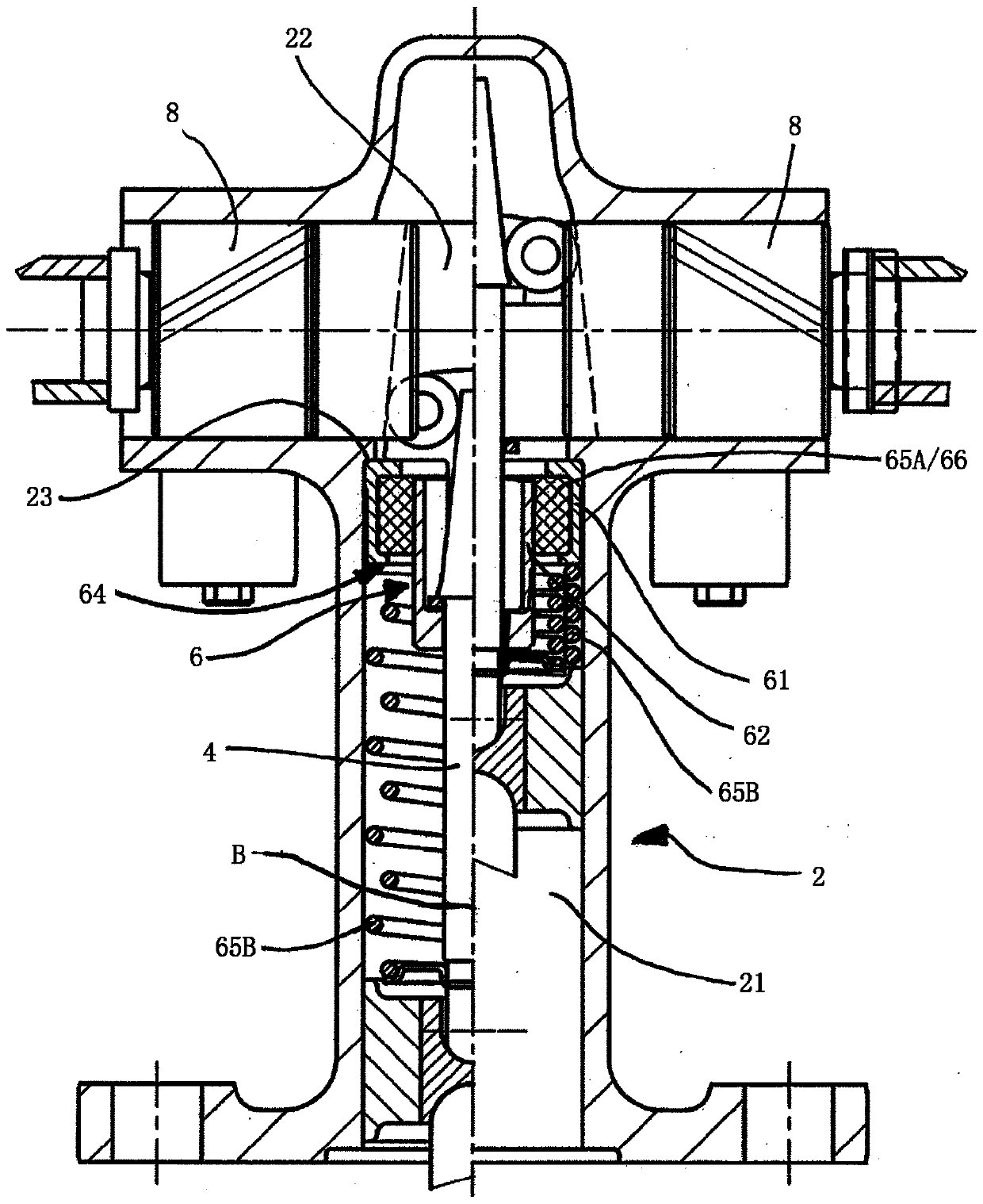
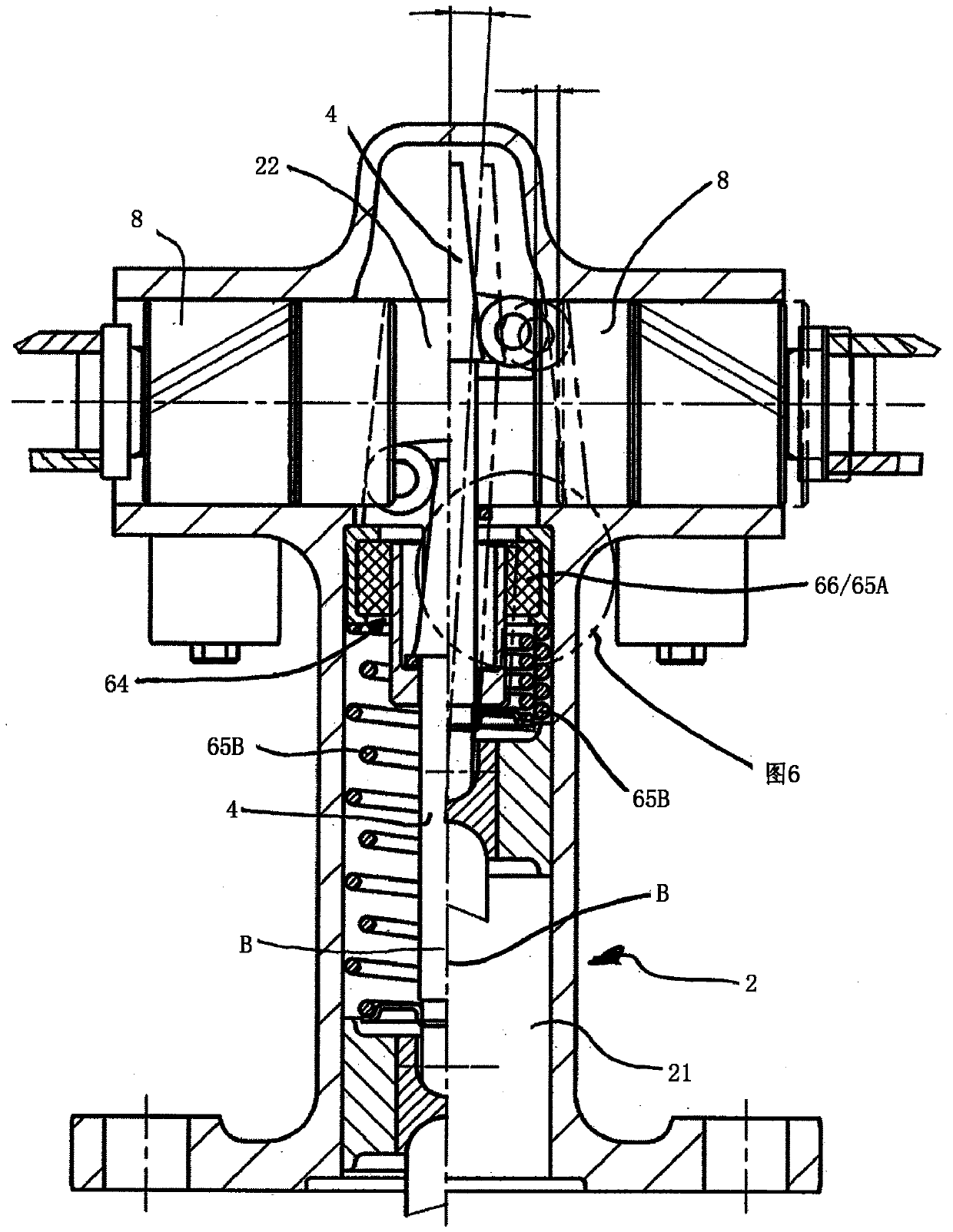
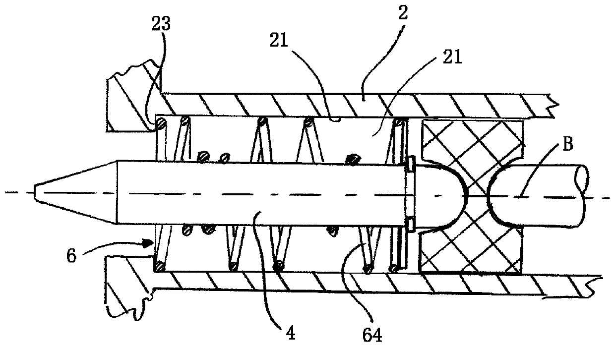
[0026] figure 1 and figure 2 The preferred embodiment of the expansion wedge unit shown in has a housing 2 with a first housing region 21 and a second housing region 22 . Preferably, the first housing region 21 is substantially cylindrical and extends along the actuation axis B with a substantially constant cross section. figure 1 and figure 2 The left half of , shows the state of the expanding wedge unit in which the expanding wedge extends maximally from the second housing region 22 , ie in the non-actuated state of the brake. The corresponding right half of the figure shows the state in which the expansion wedge is maximally retracted into the second housing area 22 and thus achieves a maximum deflection of the piston element 8 and the brake shoe supported thereon . The first spring member 65A is a rubber member 66 disposed between the first guide portion 61 and the second guide portion 62 . The second spring element 65B is a helical spring with windings of different...


PUM


Abstract

The present invention relates to an expansion wedge unit, comprising a housing (2), an expansion wedge (4) and a guiding unit (6), wherein the guiding unit (6) and the expansion wedge (4) can be arranged in a first housing region (21) of the housing (2), wherein the guiding unit (6) is supported with a first guiding portion (61) on a wall of the first housing region (21) in such a way that it is secured against shifting and pivoting in relation to the housing (2) transversely to the axis of actuation (B), wherein the expansion wedge (4) is guided in a second guiding portion (62) of the guidingunit (6), wherein a restoring region (64), which allows a sprung relative movement between the first guiding portion (61) and the second guiding portion (62), is provided between the first guiding portion (61) and the second guiding portion (62).

Description

technical field [0001] The invention relates to an expanding wedge unit, in particular for a drum brake of a truck. Background technique [0002] Expanding wedge units are known in the prior art. The expanding wedge is used to press one or two pistons, usually via force-transmitting rollers, against the brake shoes or pads of the brake system, which in turn are pressed against the inside of the brake disc or drum brake. In drum brakes, one of the two brake shoes has a so-called self-energizing effect, where in this case the rising brake shoe, i.e., is loaded with tangential friction directed towards its point of rotation In addition to the expansion force pressed against the brake drum, the brake shoe is loaded with other forces. This effect means that the two brake shoes transmit different degrees of reaction force to the expansion wedge, causing the expansion wedge to pivot out of its original position. In order to allow this process, the expansion wedge of the drum bra...

Claims


Application Information

Patent Timeline
IPC IPC(8): F16D51/48F16D65/22
CPCF16D51/48F16D65/22F16D2125/66
Inventor 托比亚斯·蔡斯
Owner SAF HOLLAND GMBH
Why Eureka
Try Eureka