
Control system of ejector trolley mechanism

A technology of a mandrel trolley and a control system, which is applied to the rolling mill control device, manufacturing tools, mechanical equipment, etc., can solve the problems of uneven wall of the steel pipe, the positioning seat of the trolley cannot be adjusted online, etc., and achieves simple structure, convenient operation and adjustment, The effect of high stability and reliability

Active Publication Date: 2021-10-19
TAIYUAN HEAVY IND
View PDF5 Cites 0 Cited by
  • Summary
  • Abstract
  • Description
  • Claims
  • Application Information

AI Technical Summary

Problems solved by technology

[0004] Due to the high pressure on the ejector rod during the rolling process of the steel pipe, the existing ejector trolley mechanism adopts the motor screw drive mode to adjust the position of the trolley positioning seat, so as to adjust the ejector trolley and the ejector rod installed on it. The position of the plug and the plug cannot be adjusted online, but can only be adjusted offline; since the positioning seat of the trolley cannot be adjusted online, the rolling pass will change due to the temperature change of the plug and the roll during the rolling process, resulting in the rotation after expansion. The wall of the steel pipe is uneven

Method used


Image

  • Control system of ejector trolley mechanism
  • Control system of ejector trolley mechanism
  • Control system of ejector trolley mechanism

Examples


Embodiment Construction

[0041] In order to make the purpose, technical solution and advantages of the present invention clearer, the technical solution of the present invention will be clearly and completely described below in conjunction with specific embodiments of the present invention and corresponding drawings. Apparently, the described embodiments are only some of the embodiments of the present invention, but not all of them. Based on the embodiments of the present invention, all other embodiments obtained by persons of ordinary skill in the art without making creative efforts fall within the protection scope of the present invention.

[0042] The technical solutions provided by the embodiments of the present invention will be described in detail below in conjunction with the accompanying drawings.

[0043] as attached Figure 4-9 As shown, the ejector trolley mechanism control system provided by the present invention is used to adjust the position of the trolley positioning seat D2 in the eje...


PUM


Abstract

The invention discloses a control system for a push rod trolley mechanism. The control system includes: a hydraulic cylinder, a servo valve control assembly, a directional valve control assembly, a detection module and a control module; one of the fixed end and the output end of the hydraulic cylinder is connected to the base of the ejector trolley mechanism, and the other is connected to the positioning seat of the trolley; The servo valve control component and the directional valve control component are respectively connected to the two inner chambers of the hydraulic cylinder, and form a hydraulic control circuit with the system pressure oil, system return oil and system drain oil, which are used to control the position and moving speed of the output end; the detection module is used It is used to detect the position and moving speed of the head of the ejector trolley mechanism; the control module is respectively connected to the servo valve control component, the directional valve control component and the detection module, and is used to control the servo valve control component and the directional valve control component according to the detection results of the detection module. The ejector trolley mechanism control system of the present invention can perform on-line and off-line adjustments to the position of the rotary expansion machine head according to the requirements of the rolling process.

Description

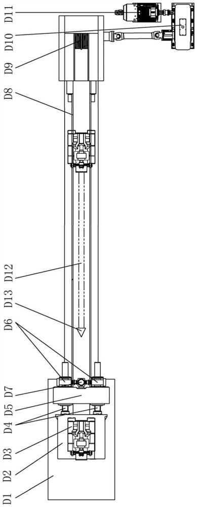
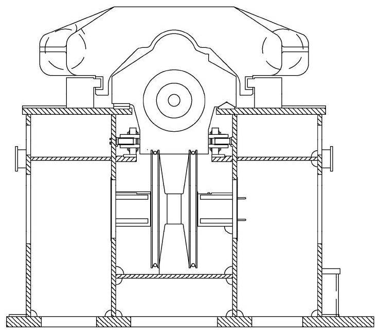
technical field [0001] The invention relates to the technical field of steel rolling production equipment, in particular to a control system for a push rod trolley mechanism. Background technique [0002] The main function of the ejector trolley mechanism of the steel pipe rotary expansion machine is to limit and position the position of the top of the steel pipe rotary expansion machine to determine the pass shape of the rolled steel pipe. figure 1 It is a top view structural schematic diagram of a push rod trolley mechanism in the prior art; figure 1 and attached Figure 2-3 As shown, the ejector trolley mechanism in the prior art includes: base D1, trolley positioning seat D2, ejector trolley D3, adjusting screw D4, screw mounting seat D5, worm gear reducer D6, screw drive motor D7, Wire rope D8, wire rope reel D9, reducer D10 and reducer drive motor D11; trolley positioning seat D2 is installed on the slide rail of base D1 through the slideway, screw mounting seat D5 i...

Claims


Application Information

Patent Timeline
Patent Type & Authority Patents(China)
IPC IPC(8): B21B25/00B21B25/02B21B37/78F15B13/02F15B1/02
CPCB21B25/00B21B25/02B21B37/78F15B1/02F15B13/02
Inventor 曹美忠刘涛张力畅兴刚陈晋峰周新亮臧树林
Owner TAIYUAN HEAVY IND
Learn More