Eureka AIR delivers breakthrough ideas for toughest innovation challenges, trusted by R&D personnel around the world.

Ejection mechanism

An ejection mechanism and ejection technology, applied in the direction of metal processing, metal processing equipment, manufacturing tools, etc., can solve the problems of spending a lot of time, the burden of motor manufacturing enterprises, and difficulty in removing quickly, and achieve the goal of improving disassembly efficiency Effect

Inactive Publication Date: 2020-05-19
安徽中巨智能科技有限公司
View PDF0 Cites 2 Cited by
  • Summary
  • Abstract
  • Description
  • Claims
  • Application Information

AI Technical Summary

Problems solved by technology

[0002] Medium-sized stepping motors are very common in various equipment and in production and life, so the motor has a broad application prospect in the waste field. The stator core in the motor and the copper enameled wire on the stator winding can be recycled. Therefore, the stator and Winding recovery is an important application direction. Since the stator winding is wound in the winding slot of the stator core, it is difficult to quickly remove it by simply clamping it with a wrench or pliers, and it takes a lot of time to separate the stator winding and the iron core. , so the winding recovery efficiency of the stator core is extremely low, and there is a certain burden on the motor manufacturing enterprises

Method used


Image

  • Ejection mechanism
  • Ejection mechanism
  • Ejection mechanism

Examples


Embodiment Construction

[0029] In order to make the objects and advantages of the present invention clearer, the present invention will be described in detail below in conjunction with the examples. It should be understood that the following words are only used to describe one or several specific implementation modes of the present invention, and do not strictly limit the protection scope of the specific claims of the present invention. As used herein, the terms "parallel" and "perpendicular" are not limited to their strict geometric definitions, but include reasonable and inconsistent tolerances for machining or human error;

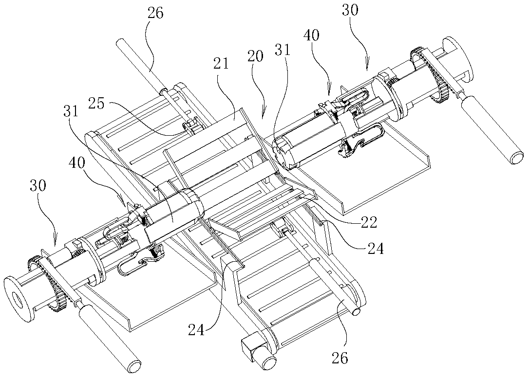
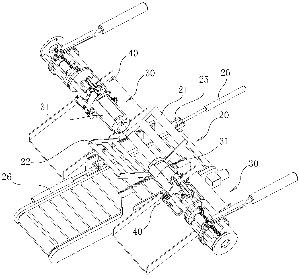
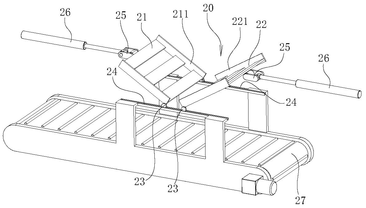
[0030] The ejector mechanism of the present invention will be described in detail below in conjunction with the entire motor winding dismounting device:

[0031] The specific features of the motor winding removal device are described in detail below:

[0032] A motor winding removal device, comprising a stator conveying mechanism 10, a stator core fixing mechanism 20 is provi...


PUM


Abstract

The invention relates to an ejection mechanism. the ejection mechanism comprises a stator and stator core mechanism. An ejection mechanism body is arranged beside the stator and stator core mechanism.The ejection mechanism body comprises an ejection head. The length direction of the ejection head is horizontal. An expansion ring is arranged on the outer wall of the ejection head. The ejection head is driven by the horizontal ejection mechanism to move, and is in plug fit with a stator of the stator and stator core mechanism. The ejection head is inserted into the stator, and the outer diameter of the expansion ring is increased. A waste stator winding is conveyed into the stator and stator core mechanism through a stator conveying mechanism. The stator and stator core mechanism is used toimplement operation on the stator core of the stator by utilizing the stator and stator core mechanism. it is convenient for the ejection mechanism body to unfold the stator windings to enable the stator windings to be flat, and then a winding clamping mechanism is used to implement clamping on windings at the two ends of the stator to implement separation between the stator core and the windings. With the ejection mechanism for detachment, the efficiency of detachment between the stator windings and the stator core can be effectively improved.

Description

technical field [0001] The invention relates to the technical field of processing waste electric motors, in particular to an ejection mechanism. Background technique [0002] Medium-sized stepping motors are very common in various equipment and in production and life, so the motor has a broad application prospect in the waste field. The stator core in the motor and the copper enameled wire on the stator winding can be recycled. Therefore, the stator and Winding recovery is an important application direction. Since the stator winding is wound in the winding slot of the stator core, it is difficult to quickly remove it by simply clamping it with a wrench or pliers, and it takes a lot of time to separate the stator winding and the iron core. , so the winding recovery efficiency of the stator core is extremely low, and there is a certain burden on the motor manufacturing enterprises. Contents of the invention [0003] The purpose of the present invention is to provide a eject...

Claims


Application Information

Patent Timeline
IPC IPC(8): B23P19/027B23P19/00
CPCB23P19/006B23P19/027
Inventor 不公告发明人
Owner 安徽中巨智能科技有限公司
Why Eureka
Eureka Blog
Learn More