Screen mounting leveling tool and method

A technology for leveling tools and screens, applied in the direction of manufacturing tools, hand-held tools, etc., can solve problems affecting use, screen height difference, etc.

Active Publication Date: 2020-05-19
XIAN QINGSONG PHOTOELECTRIC TECH CO LTD
View PDF10 Cites 0 Cited by
  • Summary
  • Abstract
  • Description
  • Claims
  • Application Information

AI Technical Summary

Problems solved by technology

[0003] Based on this, the object of the present invention is to provide a screen installation and leveling tool to solve the technical proble

Method used


Image

  • Screen mounting leveling tool and method
  • Screen mounting leveling tool and method
  • Screen mounting leveling tool and method

Examples


Embodiment 1

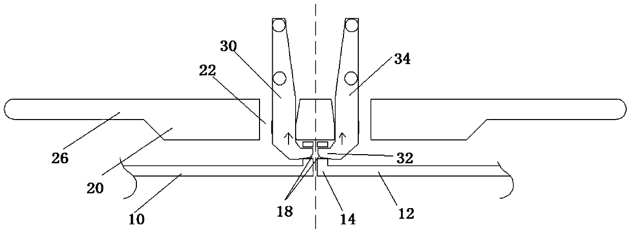
[0028] The embodiment of the present invention provides a screen installation leveling tool, please refer to image 3 , image 3 It is a working diagram of the screen installation leveling tool according to Embodiment 1 of the present invention. As shown in the figure, the screen installation leveling tool includes a leveling base plate 20 and at least two hooks 30, and the leveling base plate 20 includes a first surface and a second surface. Two sides, wherein the first side is a plane. At least two second through holes 22 are opened on the leveling substrate 20, and the second through holes 22 are arranged in pairs; the pull hook 30 includes a fixedly connected hook portion 32 and a pulling portion 34; when the screen installation leveling tool is in the In the working state, the leveling substrate 20 is located above the LED box 10 and the first surface is facing the side of the LED box 10, and the hook 32 can pull the LED box 10 to move up and make the top surface of the ...

Embodiment 2

[0032] Please refer to Figure 4 , Figure 4 It is a working schematic diagram of the screen installation and leveling tool described in Embodiment 2 of the present invention. The screen installation leveling tool according to Embodiment 2 of the present invention includes a leveling base plate 20 , at least two pull hooks 30 , a first pressing rod 40 and at least two hinged supports 24 . At least two second through holes 22 are opened on the leveling substrate 20 , and the second through holes 22 are arranged in pairs. As a preferred implementation mode, in this embodiment, the number of the second through holes 22 is two.

[0033] The draw hook 30 includes a fixedly connected hook portion 32 and a pull portion 34 , the hook portion 32 can pull the LED box 10 to move up and down, and the pull portion 34 can move up and down through the second through hole 22 . As an optional implementation, in order to facilitate the pull hook 30 to pull the LED box, the frame structure of ...

Embodiment 3

[0039] Please refer to Figure 6 , Figure 6 It is a schematic diagram of the working structure of the screen installation and leveling tool described in Embodiment 3 of the present invention. As shown in the figure, the embodiment of the present invention provides a screen installation leveling tool, which is different from Embodiment 2 in that it also includes a second pressing rod 50, and the second pressing rod 50 includes at least two second pressing rod bodies 52, the second pressing rod body 52 is fixedly connected with the pulling part 34, by pulling up the second pressing rod body 52, that is, each pair of second pressing rod bodies 52 exerts a force toward the direction of approaching each other, and then passes through the pulling part 34 exerts a force to compress the elastic member 28 , so that the hook portion 32 escapes from the first through hole 18 . The second pressing rod 50 and the first pressing rod 40 cooperate with each other, so that the insertion and...


PUM


Abstract

The embodiment of the invention relates to a screen mounting leveling tool. A screen is formed by splicing and fixing at least two LED boxes, the screen mounting leveling tool comprises a leveling base plate and at least two pull hooks; and the leveling base plate comprises a first surface, the first surface is a plane, the leveling base plate is provided with at least two second through holes, and the pull hooks each comprise a hook part and a pulling part which are fixedly connected. When the screen mounting leveling tool is in a working state, the leveling base plate is located above the two adjacent LED boxes, the first surface faces one sides of the LED boxes, the pulling parts can penetrate through the second through holes in an up-down moving mode, the pull hooks can pull the LED boxes to move up and enable the top surfaces of the LED boxes to abut against the first surface, the mutually fixed positions of positioning pins and positioning pin holes and the mutually fixed positions of lock catches and lock catch buckling positions are finely adjusted, and the height drop of a screen body due to the accumulated mechanical tolerance is eliminated.

Description

technical field [0001] The invention relates to the technical field of electronic display equipment production, in particular to a screen installation and leveling tool and a screen installation and leveling method. Background technique [0002] The LED display screen in the prior art is formed by splicing two or more LED display boxes. A single LED box includes a bottom plate and a side wall fixed to the edge of the bottom plate. The inside of the LED box can also be set There are several ribs. In the conventional design, the splicing of LED display screens is to set positioning pins and locks on the outside of the side wall of a single LED box. There are lock buckle positions, and multiple LED cabinets are spliced ​​and fixed through the mutual cooperation of positioning pins and positioning pin holes, lock buckles and lock buckle positions. However, this splicing and fixing method has certain tolerances due to the size and relative position of the positioning pin and th...

Claims


Application Information

Patent Timeline
IPC IPC(8): B25B27/00
CPCB25B27/00
Inventor 彭文明
Owner XIAN QINGSONG PHOTOELECTRIC TECH CO LTD
Why Eureka
Try Eureka