Clamping platform on ceramic cutting machine

A cutting machine and clamping technology, applied in the direction of stone processing tools, work accessories, manufacturing tools, etc., can solve the problems of cumbersome clamping, low efficiency, cumbersome clamping operation, etc., and achieve the effect of simple clamping structure.

Inactive Publication Date: 2020-05-19
苏州哲思达智能设备科技有限公司
View PDF0 Cites 1 Cited by
  • Summary
  • Abstract
  • Description
  • Claims
  • Application Information

AI Technical Summary

Problems solved by technology

At present, some ceramics, such as ceramic tiles, after a series of surface treatments such as firing, polishing, etc., according to the requirements of production specifications, it is necessary to cut the whole piece of ceramic tiles into small tiles of the required specifications. The current tile cutting Generally, it is carried out on a ceramic cutting machine, which has a movable placement platform and a fixed cutting wheel mechanism; while fixing tiles on the existing placement platform requires a clamping device, the existing clamping device, such as a general L-shaped clamping block, requires There are multiple L-shaped clamps fixed on the periphery of the tiles, which is troublesome to clamp; especially after a cutting is completed, the L-shaped clamps are disassembled and reinstalled, the clamping operation is cumbersome and the efficiency is not high

Method used


Image

  • Clamping platform on ceramic cutting machine
  • Clamping platform on ceramic cutting machine
  • Clamping platform on ceramic cutting machine

Examples


Embodiment

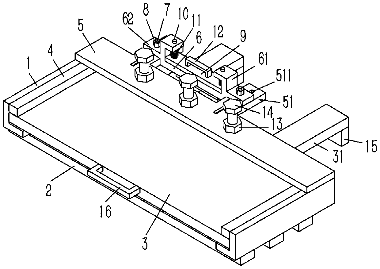
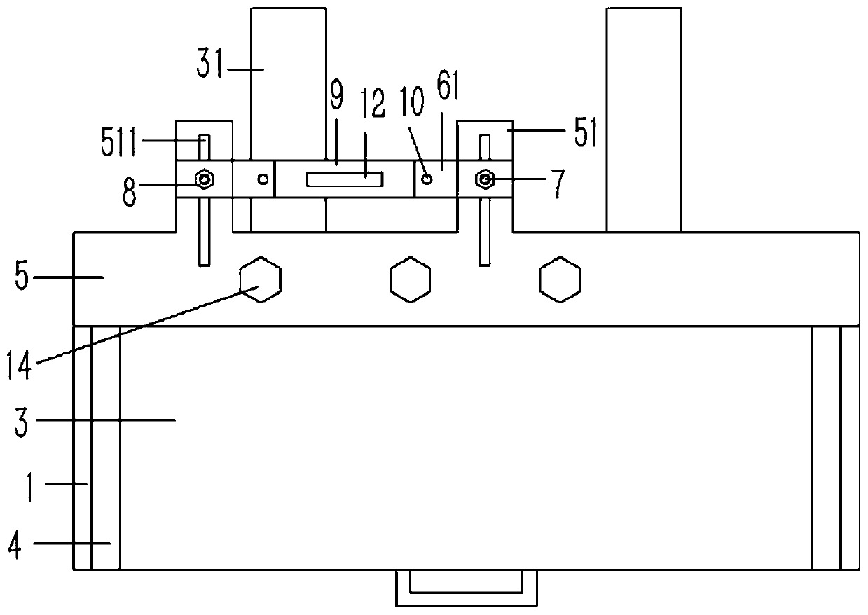
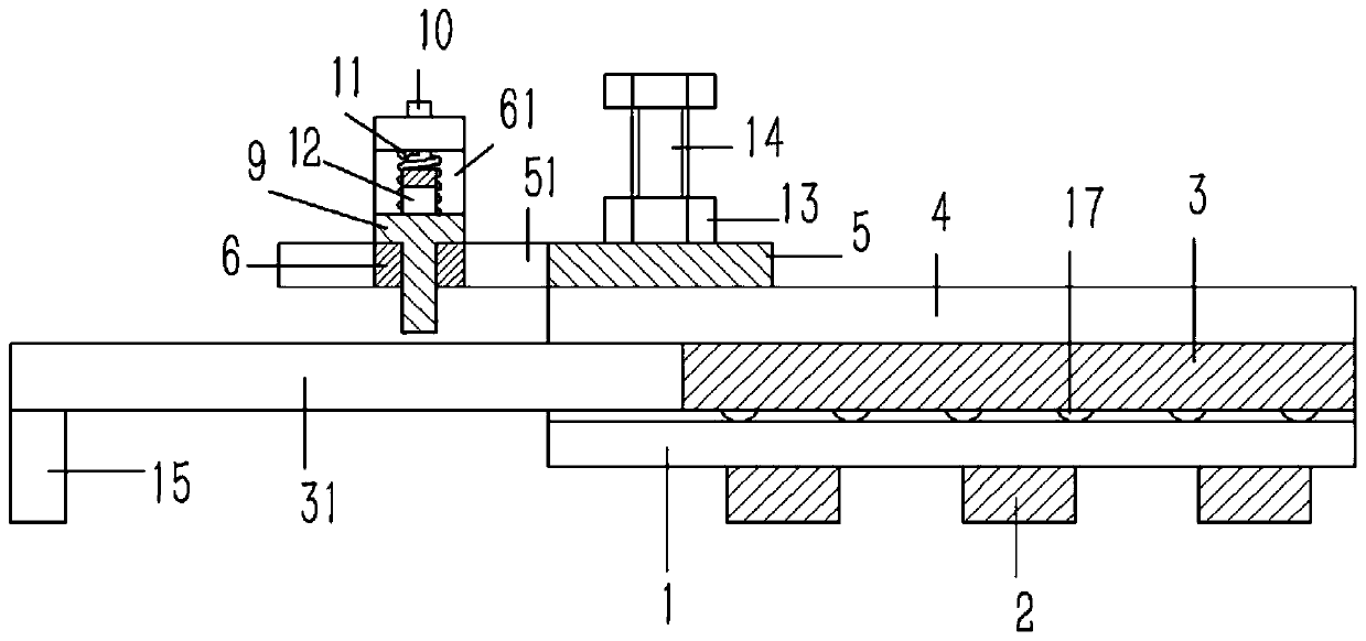
[0019] Example: see Figures 1 to 3 As described above, a clamping platform on a ceramic cutting machine includes two sets of longitudinal L-shaped side brackets 1, the side brackets 1 are composed of vertical parts and horizontal parts, and the lower end surface of the side brackets 1 is fixedly connected with several horizontal There is a sliding platform 3 between the bottom bar 2 and the side bracket 1, the sliding platform 3 is against the horizontal part of the side bracket 1, the upper end surface of the sliding platform 3 is against the limit bar 4, and the limit bar 4 is fixed On the vertical part of the side bracket 1, the upper end surface of the rear end of the side bracket 1 is fixedly connected with a horizontal positioning plate 5, and a plurality of clamping bolts 14 are inserted on the positioning plate 5, and the clamping bolts 14 are screwed to the fixed nut 13, Fixed nut 13 is fixed on the positioning plate 5;

[0020] The rear end surface of the sliding p...


PUM


Abstract

The invention discloses a clamping platform on a ceramic cutting machine. The clamping platform comprises two sets of longitudinal L-shaped side brackets; the side brackets are composed of vertical parts and horizontal parts; a plurality of transverse bottom rods are fixedly connected to the lower end surface of each side bracket; a sliding platform is arranged between the side brackets, and is propped against the horizontal parts of the side brackets; limiting barrier strips are propped against the upper end surface of the sliding platform, and are fixed on the vertical parts of the corresponding side brackets; a transverse positioning plate is fixedly connected to the upper end surfaces of the rear ends of the side brackets; a plurality of clamping bolts are inserted into the positioningplate, and are in screw joint onto fixed nuts; and the fixed nuts are fixed on the positioning plate.

Description

technical field [0001] The invention relates to the technical field of ceramic production equipment, in particular to a clamping platform on a ceramic cutting machine. Background technique [0002] The current production process of ceramics includes blank preparation, mold making, molding, drying, glazing, firing, decoration and packaging. At present, some ceramics, such as ceramic tiles, after a series of surface treatments such as firing, polishing, etc., according to the requirements of production specifications, it is necessary to cut the whole piece of ceramic tiles into small tiles of the required specifications. The current tile cutting Generally, it is carried out on a ceramic cutting machine, which has a movable placement platform and a fixed cutting wheel mechanism; while fixing tiles on the existing placement platform requires a clamping device, the existing clamping device, such as a general L-shaped clamping block, requires There are multiple L-shaped clamps fi...

Claims


Application Information

Patent Timeline
Patent Type & Authority Applications(China)
IPC IPC(8): B28D1/22B28D7/04B28D7/00
CPCB28D1/22B28D7/00B28D7/04
Inventor 胡惠娟
Owner 苏州哲思达智能设备科技有限公司
Why Eureka
Try Eureka